Experimental Hutch
 |
| Get detailed drawing of the Experimental hutch |
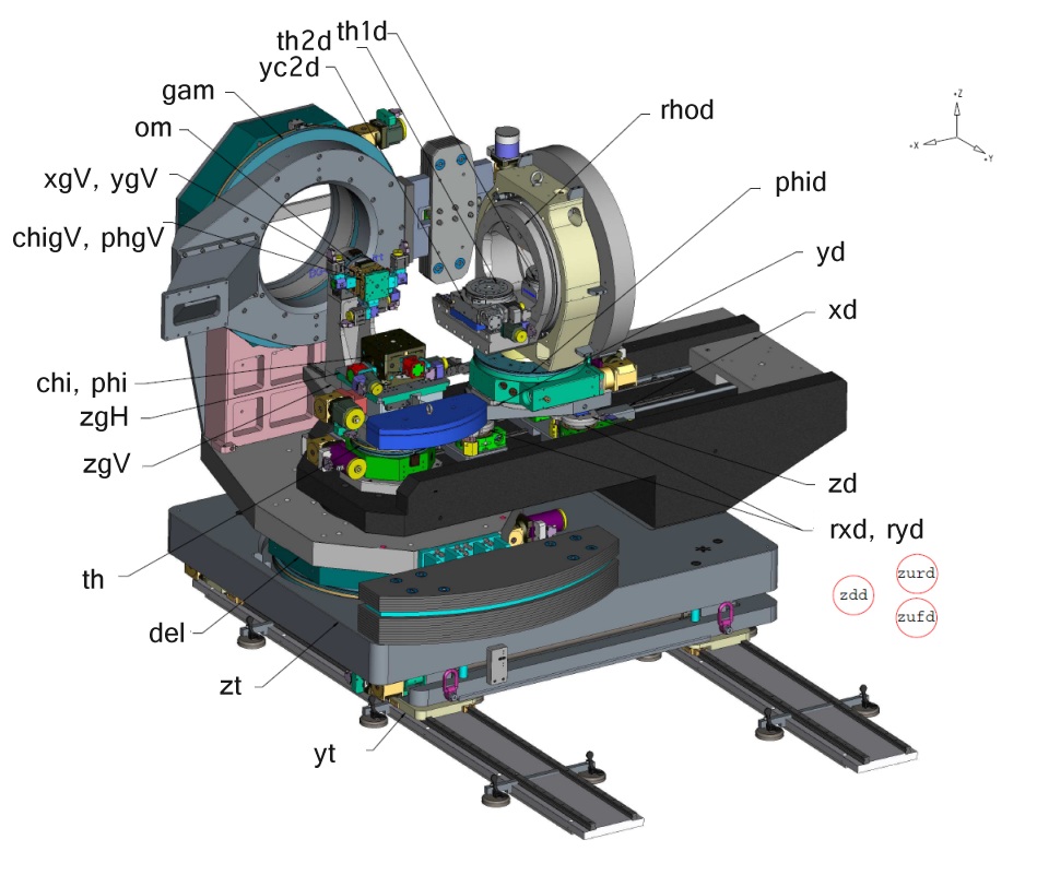
The Troïka II diffractometer [8-circle diffractometer axis names] | [8-circle diffractometer sample stages] is a multi-purpose instrument which is optimized for scattering from surfaces and interfaces using grazing-incidence diffraction and reflectivity in both the horizontal and the vertical scattering geometry. The detector arm has both horizontal and vertical axes and can be equipped with various detectors.
The sample stages were designed to maximize the available volume for sample environments. The horizontal sample stage (see Huber 5202 stage in Figure 1) consists of a horizontal turn table, a height translation and crossed arcs. In combination with the deflector this stage has a six-circle or z-axis configuration. The horizontal stage is primarily used for scattering from liquid interfaces. Furthermore heavy sample environments up to 100 kg can be supported without counterweighting. A hemispherical volume of 450 mm diameter is available for sample environments. The sample position is 170 mm from the top of the crossed arcs. Optionally a xy-translation stage can be added on top of the arcs. In this case the sample position is 110 mm from the top of the xy-translation stage.
The vertical scattering stage (see Huber 5204 stage on Figure 1) comprises a vertical turntable and a long translation which permits the removal of this stage from the scattering position, if necessary. This stage is controlled by a 2+2 code (two detector axes and two sample axes). Additionally the sample goniometer has crossed arcs to line up the surface normal and two more translations. It can be used for small experimental set-ups of less than 2 kg and 250 mm diameter. The sample position is at 110 mm from the top plate of the crossed arcs.
 |
|
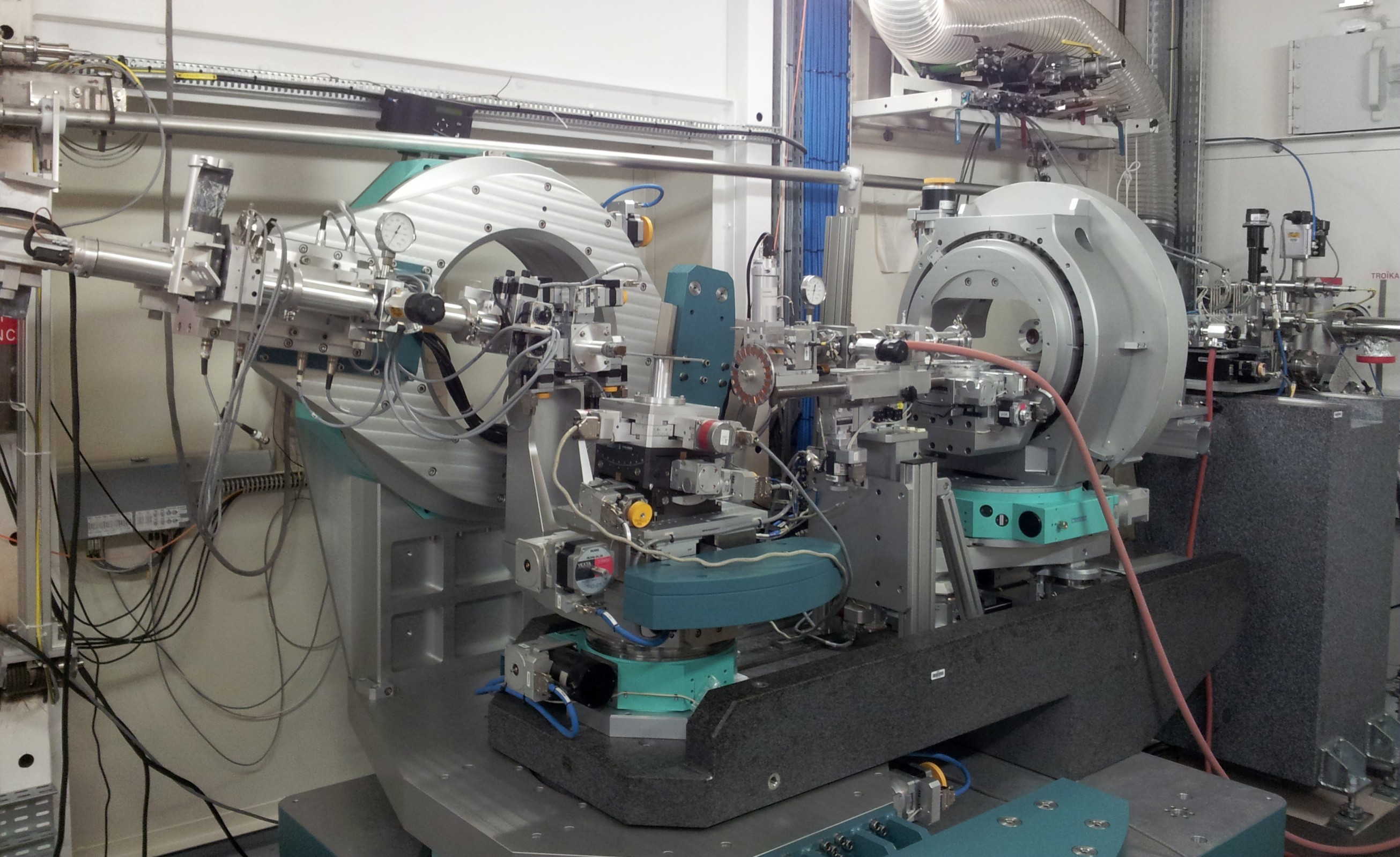
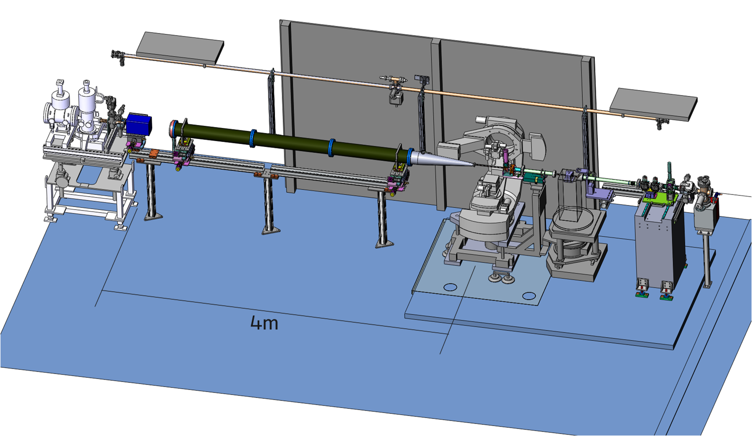
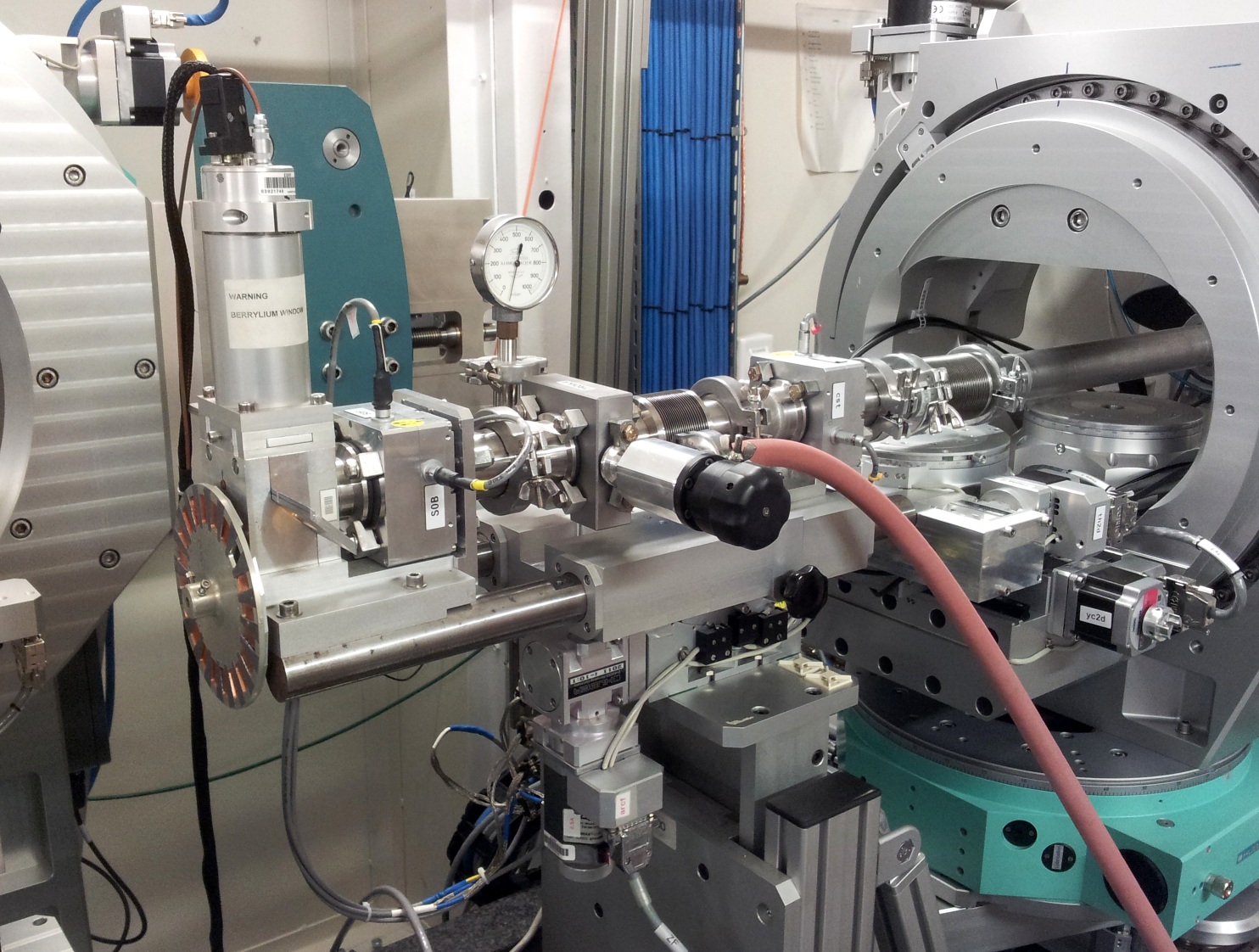
Fig. 1: Schematic view of the ID10-EH1 diffractometer combined with the double crystal beam deflector (see photo). The X-ray beam passes from right to left along X-axis. |
The detector arm has three possible configurations: The default configuration comprises an MicroControle X48 optical bench, motorized front slits, variable length flight path with Kapton windows and motorized detector slits. Either a scintillation detector or a Kapton detector can be used with this set-up. Alternatively the X48 bench can be equipped with a 150 mm Soller collimator of 1.4 mrad resolution and a 150 mm or 50 mm linear gas detector for the horizontal scattering configuration.
The second configuration consists of an analyzer stage. In horizontal scattering geometry a 150 mm Si(111) analyzer crystal can be combined with a 150 mm linear gas detector. In vertical scattering geometry various 50 mm analyzer crystals can be combined with a 50 mm linear gas detector.
The third configuration of the detector arm provides a mount for a MicroControle X95 profile which can be used for equipment that was originally designed for the Troïka I station. In this configuration X95 profile serves as a flightpath and a holder for collimation slits (JJ X-ray slits) and a detector.
The diffractometer can be equipped with a sealed Langmuir trough that is mounted on the top of active antivibrational system MOD-2 S fixed on horizontal stage. A conventional 2-circle analyser stage can be installed on detector arm.
The Experimental Hutch is air-conditioned and provides basic supplies (pressurised air and He gas from a bottle). A water purifying system is available on request. Simple sample-environment equipment and space for preparation of experiments is available in an adjacent laboratory.
Important information for planning of non standard experiments. The maximum sample-detector distance is 1.5m, when detector is mounted on the detector arm of the diffractometer. This distance can be increased up to 4m if detector is mounted on the rail going along the optical axis of the beamline (see drawing).
Incident Flight Path
The incident flight path comprises an upstream slits (CS), an evacuated tube, the down streem slits (S0), the incident beam monitor and an attenuator wheel on the sample side. Both slits are in-vacuum and motorized. This pair of slits is used for the beam collimation and its clean up. The incident beam intensity is monitored by a scintillation detector, that stays at 90 deg to the beam and measures scattering from a thin 80 or 12.7 microns Kapton foil. Variable apertures in front of the detector ranging from 0.5mm to 2mm allow the adjustment the of scattered photon flux to the dynamic range of the detector. The final optical element on the flight path is an attenuator wheel consisting of 20 slots which can be filled with foils of Al, Si, V or Cu. Initial slot (#0) is empty. The first slot (#1) has one foil of thickness D. The second slot (#2) has two foils of thickness D, so the total thickness is 2*D. Slot #N has N foils which give thickness N*D. Incrimental change of the foils number allows smoothly vary the intensity on detectors and to keep the radiation dose on sensitive organic samples at desired level. Available thiknesses of foils are 100microns (Al), 200 microns (Si), 40 microns (V), Cu (46 microns (Cu) and 125 microns (Cu). Pneumatic filters inserter XIA (usually used with Al or Cu foils of different thickness) can be used additionally to the beam attenuation as a local shutter to protect sensitive samples from the X-ray beam on a time of motors motion between two points of acquisition.
EH1 hutch beging with the table which holds three invacuum elemnets: fast shutter and two electropneumatic attenuators. Fast shutter controlled with the spec application eh1_opiom can work in three modes: stay closed, stay opend and be opened only for counting time. Electropneumatic attenuators are additonal means of beam atenuation. One set has Al foils (ncremental step 100 micron). Another set has Cu foils (incremental step 46 micron). Foils number can be chaned from 0 to 15.
Data Acquisition and Beamline Control
The beamline is controlled with MAX workstation. MAX is a computer working under Linux and connected to the Ethernet. Stepping motors, encoders and detectors are driven via ICEPAPs. Monochromator, deflector, and diffractometer are controlled by the SPEC software package from Certified Scientific Software. In horizontal scattering geometry the diffractometer can be positioned in six-circle mode or z-axis mode. For the vertical scattering geometry a 2+2 code can be used.
Avaialble detectors at ID10-EH1 are scintillation counters, linear position sensitive detector (60mm Mythen-1K with 50 µm spatial resolution), MAXIPIX 1x5 and silicon drift detector Vantec-EM with the sensor area 50mm2. Other detectors can be used upon its availability at the detector pool.
Basic data evaluation can be performed on MAX or on the Windows PC located in the EH1 control hutch. Data from the workstation can be directly accessed from the Windows PC. Some basic software for data analysis and commercial software packages are available on the MAX workstation and on the Windows PC.
partners


![[8-circle diffractometer axis names]](/files/live/sites/www/files/UsersAndScience/Experiments/SoftMatter/ID10/ID10EH1/UsersGuide/exphut/axis-names.gif)
![[8-circle diffractometer sample stages]](/files/live/sites/www/files/UsersAndScience/Experiments/SoftMatter/ID10/ID10EH1/UsersGuide/exphut/sample-stages.gif)
European Synchrotron Radiation Facility - 71, avenue des Martyrs, CS 40220, 38043 Grenoble Cedex 9, France.