- Home
- Users & Science
- Scientific Documentation
- ESRF Highlights
- ESRF Highlights 2016
- Accelerator and Source
Accelerator and Source
The Accelerator and Source Division (ASD) is in charge of the production of synchrotron light from the ESRF’s 6 GeV storage ring. Much of the division’s development work in 2016 has been focused on the ESRF-EBS, and major progress has been made in design and procurement, with the first components already arriving on site, as already detailed in the ‘Status of the EBS’ section of this report. Despite the challenges faced by the increased workload of the project, the division has also continued to ensure excellent machine availability and reliability throughout 2016, including running preventative maintenance campaigns to replace ageing equipment, developing new diagnostics devices, installing new in-vacuum undulators and maintaining the high quality power supplies.
As a result of these efforts, the operation statistics for 2016 are very positive. A total of 5485 hours of beam was delivered out of 5537 scheduled hours, representing an excellent availability of 99.06% and coming very close to the ESRF’s all-time record (99.11%). The mean time between failures (MTBF) was high, at an average of 93.8 hours. More information on the main parameters of the storage ring can be found at the end of this chapter in Appendix 1.
In April 2016, for the first time, refill in top-up mode was delivered to users, providing better beam stability, low vertical emittance in all filling modes and a nearly constant beam current. The implementation followed several years of upgrades and modifications to the machine, including, in 2016, a new timing sequence, the development of cleaning in the booster and the start of commissioning of the new ramped injection power supply for the booster. Feedback from the beamlines was extremely positive and top-up is set to be improved even further in 2017 when the new booster power supply is put into operation.
The ESRF also hosted the ninth Continuous Wave and High Average RF Power (CWRF) Workshop in June 2016. The workshop provided an opportunity for designers and users of high-power CWRF systems to share experience, ideas and developments for such systems.
This year’s achievements would not have been possible without the dedication of the ASD staff and the continuous support of the other ESRF divisions. May this continue in 2017 as we face the challenges of entering the assembly phase of the ESRF-EBS while simultaneously ensuring optimal operating conditions for our users.
P. Raimondi
Summary of accelerator operation
With 5485 hours of beam delivered out of 5537 scheduled hours, the overall availability reached 99.06% compared to 98.53% in 2015. This high level of availability (as a reminder, the all-time record was 99.11% in 2014) reveals the success of a global preventive maintenance programme leading to the absence of very long failures in 2016.
Moreover, this year, we must emphasise the excellent reliability of the injectors. Indeed, every year, the number of refills in user mode is close to 560. This year, due to the several weeks delivered in top-up mode, the number of refills reached more than 4100. This is as many refills as are generally carried out in seven years! Except for a very low percentage (~ 3%) of skipped refills for minor reasons, the linac and the booster demonstrated their robustness thanks to an effective overhaul of the system and improvement of their components.
Over the year, only four trips lasted more than three hours: two of them attributed to the vacuum (one PLC power supply failure lasting 3.5 hours and one fugitive interlock due to a damaged cable lasting 3 hours) and two attributed to the radio frequency system (one tuner problem lasting 3.5 hours and a PLC power supply failure of 3.25 hours). Meriting a special mention is the second run, in which availability reached 99.75%, while 1508 refills in total took place for the first USM operation with top-up mode. The mean time between failures in 2016 reached 94 hours, exactly the same figure as in 2015.
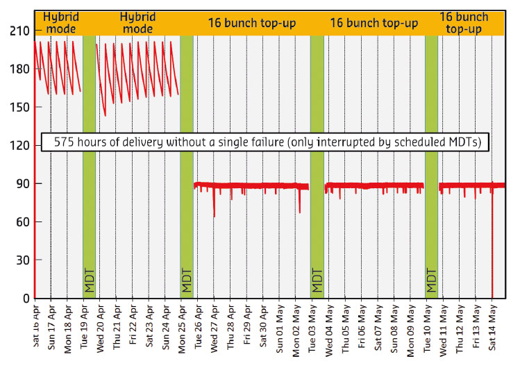
Once again, the second run was the standout of the year since only five failures occurred during the 1287 hours of USM, giving an exceptional MTBF of 257 hours over the run. It was also during this run that the longest period without a failure took place (see Figure 162 below) with 575 hours of delivery in two different modes only interrupted by the scheduled machine development time (MDT).
 |
|
Fig. 162: Uninterrupted beam delivery for 24 days (575 hours) in hybrid and 16-bunch modes during the run 2016-02. This illustrates the high availability in top-up mode and near constant beam current. |
With respect to the repetitive failures, a dramatic improvement was seen in the detection of false RF arcs. From 14 arc detections in 2015 (false or real), only six were detected in 2016. The reduction was due to the successful diagnosis of the sources of the problem and corresponding corrective action. In addition, a new type of RF detector was tested for a year on an RF station. Following the successful results, 20 of the detectors (50% of the total stock) were replaced during the 2016-2017 winter shutdown, so that even fewer false arc detections should be achievable in 2017, the new detectors being based on a sophisticated system of coincidence before triggering.
A summary of storage ring operation for the year is presented in Table 1.
|
Table 1: Overview of storage ring operation in 2016. 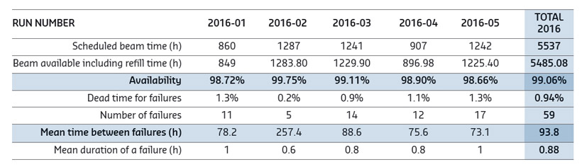 |
Filling patterns
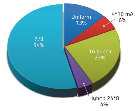
In 2016, the distribution of the modes (Figure 163) was very similar to 2015. A fundamental improvement was the delivery of seven weeks in 16-bunch and two weeks in 4*10 mA (or sometimes 8 mA), both in top-up mode. This allowed a permanent delivery with a very low vertical emittance in the 7 pm.rad range and even less on some occasions. During the runs 2016-02 and 04, the cleaning of impurities was done in the storage ring, inducing a short but visible disturbance (vertical emittance blow-up) during the cleaning.
The final touch occurred during the last run when the beam was successfully cleaned in the booster before being sent to the storage ring. This removed the last visible perturbation seen by the users during the previous runs, to their great satisfaction. More details can be found in the dedicated paragraph.
 |
|
Fig. 163: Distribution of the various filling modes in 2016. |
Progress of the top-up project
After over four years of preparatory work including major upgrades to the injector and the development of new diagnostics tools to limit disturbance to the beam, injection in top-up mode was officially launched to users in April 2016.
The new mode sees the accelerators refilled with electrons every 20 minutes rather than every four to 12 hours. This results in a much higher integrated current over a 24-hour period, meaning more photons for the users and better beam stability due to smaller current variations. It also means a low vertical emittance in all filling modes. Previously, the vertical emittance would be artificially increased in some modes in order to increase the lifetime, but the nearly constant beam current provided by top-up mode means that the emittance – and the resulting brilliance and resolution for users – no longer has to be sacrificed. The first reactions from beamlines were positive, with many benefitting from an almost constant X-ray power on the optics.
 |
|
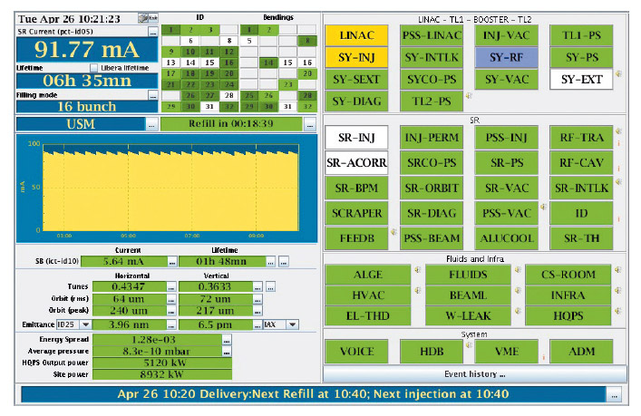
Fig. 164: The control room synopsis display on the first day of top-up operation in April 2016, showing the 20-minute injection periods and a low vertical emittance of 6.5 pm rad. |
A top-up trial period (Figure 164), with three weeks in 16-bunch mode and one week in 4*10mA mode, was run until the shutdown in May, followed by five weeks in 16-bunch and 4*8 mA throughout the rest of the year. Top-up should be further improved in 2017 once the new ramped injection power supply system (RIPS) for the booster is commissioned. Its implementation will enable cleaning to be carried out more reliably in the booster, which will further reduce disturbance to the beam during and after injection.
Launch of cleaning in the booster
In parallel with top-up injection, work to implement cleaning in the booster, instead of in the storage ring, was completed at the end of 2016. Most of the filling patterns in the storage ring necessarily include some empty buckets free of electrons. However, sometimes undesired electrons can be introduced into these buckets at an early stage of the injection process. After injection, the electron beam undergoes a ‘cleaning’ process, which consists of removing these parasitic electrons.
When performed in the storage ring, the cleaning process takes approximately 40 seconds and induces a slight disturbance of the stored beam. To avoid this disturbance during top-up operation another cleaning system has been installed in the booster, where it is possible to clean the beam in just a few milliseconds and with no disturbance to the users. It is more challenging to perform cleaning in the booster than in the storage ring because the fluctuation of the booster characteristics from cycle to cycle has to be taken into account in real time.
Before using this cleaning system in operation, all the booster parameters that could affect the quality of the cleaning were identified and tested to make sure they could be reliably controlled over the duration of a top-up operation week. In December 2016, this new system was used for the first time in operation with 16-bunch filling mode. The purity of the beam in the storage ring was constantly checked in collaboration with beamline ID18, the most sensitive beamline to beam purity, and proved to be almost perfect.
New booster power supplies
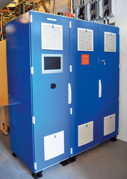
A new 4 Hz ramped injection power supply (RIPS) was developed for the booster and delivered to the ESRF in April 2016 (Figure 165). The hardware underwent site acceptance and tests with the RF and pre-injector throughout the summer, while work in the autumn focused on software debugging and current regulation. Commissioning of the equipment is nearly finalised and first operation in user mode is planned for early 2017.
 |
|
Fig. 165: The H-bridge of the new RIPS for the booster. |
Start of ten-year maintenance of HQPS
A programme of heavy maintenance was launched in autumn 2016 for the rotating machines of the high quality power supply (HQPS). This operation will be transparent for the users, and will be spread over two years. It entails a complete refurbishment of the 20 kV vital switches during the long shutdown of 2019 to enable them to be disconnected reliably from the public mains during protection sequences.
Development of a new beam loss monitoring system
The monitoring of the 6 GeV electron losses around the ESRF storage ring is presently done by a hybrid system consisting of ionisation chambers and scintillators. It allows a rough localisation of the losses, but has numerous limitations, including size, weight, time-resolution, sensitivity, versatility, and cost. A new system was developed in 2016 consisting of a detector head and the electronics for signal acquisition and control. The monitoring system is compact, based on a scintillator coupled to a small photo-multiplier module. Its volume and weight is only a fraction of the old version, allowing for easy installation.
The monitoring system controls four independent detector heads and acquires data with sampling rates up to 125 MHz and has flexible signal processing. Measurements performed on different configurations of detector head prototypes have led to an optimised design that allows a wide range of applications to be covered such as measurement of fast and strong losses as well as detection of very small variations of weak losses during the slow current decay.
After satisfactory results were obtained from prototypes installed in the injection zone and in close vicinity to in-vacuum undulators, the project of installing 128 regular units (i.e. four per cell at identical positions) plus a set (up to 30) of additional units at zones and locations of special interest is now underway (early 2017). All these units will be retained for ESRF-EBS operation.
ID straight sections
Following the installation of a canting scheme on ID15 in 2015, the straight section was completed in 2016 with two in-vacuum undulators (an IVU22 on branch A and an IVU20 on branch B), angularly separated by 4 mrad. A short wiggler with a period of 76 mm and a peak field of 1.85 T was also completed for ID15. A new helical undulator was finalised during the year and will be installed on ID12 in January 2017.
The high-performance cryogenic permanent magnet undulator, initially foreseen to be installed in the middle of the ID31 straight section at the end of 2015, was finally put into place during summer 2016. The undulator has a magnetic period of 14.4 mm and a peak field of 1 T at the minimum operating gap of 5 mm. The performance of this undulator is among the best ever reached in the world and, in particular, exceeds by far that of superconducting undulators of similar characteristics.
APPENDIX 1: Beam parameters of the storage ring
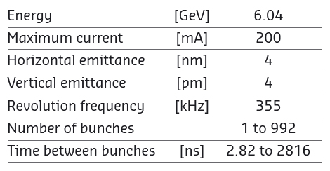
Table 2 presents a summary of the characteristics of the storage ring electron beam.
 |
|
Table 2: Principal characteristics of the electron beam. |
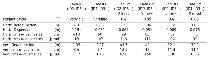
Table 3 gives the main optic functions, electron beam sizes and divergences at various source points. For insertion device source points, the beta functions, dispersion, sizes and divergences are calculated in the middle of the straight section. For bending magnets, two representative source points have been selected for each type of magnet (even or odd cell number), corresponding to magnetic fields of 0.4 T and 0.85 T. These points differ by the observation angles, of respectively 3 and 9 mrad from the entrance of the magnet.
 |
|
Table 3: Beta functions, dispersion, rms beam size and divergence at the various source points. |
Electron beam profiles are Gaussian and the size and divergence are presented in terms of rms values. The associated full width at half maximum sizes and divergences are 2.35 times higher. Horizontal electron beam sizes and divergences are given for the multibunch filling modes and apply to almost all filling patterns, except when the current per bunch is larger than 4.5 mA, for which a slightly larger size and divergence are attained because of the increased energy spread of the electron beam.
Vertical electron beam sizes and divergences are given for a vertical emittance of 4 pm, which is now the standard for 2 x 1/3 and 7/8+1 filling modes. The vertical sizes and divergences are about 1.4 times larger in uniform filling mode (due to ion effects, which are partially corrected by the use of a vertical bunch-by-bunch feedback). To increase the lifetime of the stored beam, the vertical beam sizes and divergences are deliberately increased by about a factor of 4 in the 16-bunch, 4-bunch and hybrid filling patterns.
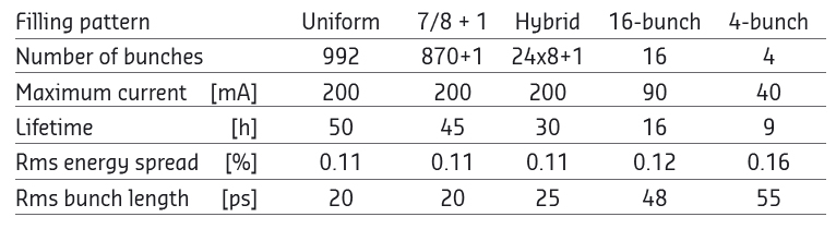
The lifetime, bunch length and energy spread mainly depend on the filling pattern. These are given in Table 4 for a few representative patterns. Note that in 16-bunch and 4-bunch filling patterns, the energy spread and bunch length decay with the current (the value indicated in the table corresponds to the maximum current). The bunch lengths are given for the usual radiofrequency accelerating voltage of 9 MV (8 MV for 16-bunch and 4-bunch).
 |
|
Table 4: Current, lifetime, bunch length and energy spread for a selection of filling modes. |
partners


European Synchrotron Radiation Facility - 71, avenue des Martyrs, CS 40220, 38043 Grenoble Cedex 9, France.