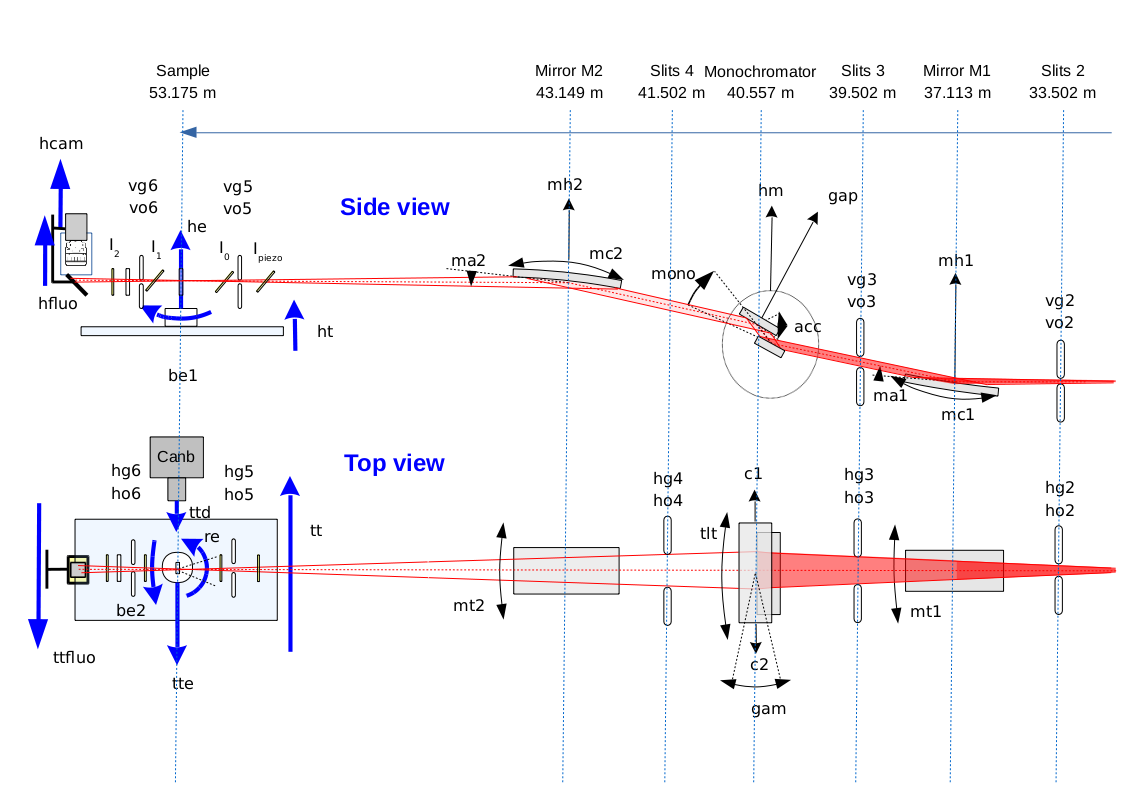
Beamline description
Optical layout

Beamline overview
This is a short description of the optical elements. For more details, see the beamline wiki.
Mirror M1
- Objectives: vertical collimation + harmonic rejection.
- Rh-coated Si rod.
- Flat bendable.
- Incidence angles: 0-7mrad.
- Optical surface: 1150x80mm.
- Water cooled.
- Escaped when working at energy higher than 22keV.
Monochromator
- Objectives: energy selection + horizontal focusing, in the range 4 - 40keV.
- Double crystal, variable exit height.
- Equiped with Si[220] (but Si[111] also possible).
- Nitrogen cooled first crystal with a setpoint at -165°C.
- Permanent feedback for parallelism optimization.
- Bendable second crystal.
Mirror M2
- Objectives: vertical focusing + harmonic rejection.
- Rh-coated Si rod.
- Flat bendable.
- Incidence angles: 0-7mrad.
- Optical surface: 1250x80mm.
- Escaped when working at energy higher than 22keV.
Slits
- Micrometric slits under vacuum - "Patisson" type - Conception and realisation : Bird & Tole
- Slits 2 and 3 are water cooled and temperature is monitored with K thermocouples:
- Calibration for K thermocouples
- Calibration for J thermocouples
- Tungsten Carbide blades thickness : 6mm.
- Radius on the working edge : 3 mm.
- Limit Switches : Baumer H75/80 (1 micron).
- Vertical slits 3 have Renishaw Readhead RGH24 encoder (resolution: 1 micron)

Sample positionning
- Height position adjusted versus the monochromator angle (precision about 1µm) via the table height (ht). Beam position on the sample is thus constant during an EXAFS scan.
- Sample holder allows:
- transverse and vertical translations
- rotation (360°)
- goniometric rotations (±7°)
Detection
- Transmission mode: diodes collecting photons scattered by air in a black chamber for both incident and transmited intensity measurements.
- Fluorescence mode: 30-element Ge detector (resolution about 300eV).


