- Home
- Users & Science
- Scientific Documentation
- ESRF Highlights
- ESRF Highlights 2000
- The X-ray Source
- Towards the Ultimate Storage Ring Based Light Source
Towards the Ultimate Storage Ring Based Light Source
The construction and successful operation of the third generation synchrotron light sources has resulted in a significant improvement in the characteristics of the X-ray beams delivered to the Users. Brilliance greater than 1020 photons/s/0.1% BW/mm2/mrad2 is currently achieved at the ESRF. Even if the trend in brilliance increase achieved over the last thirty years is over, a brilliance enhancement by two orders of magnitude can still be envisaged for an X-ray storage ring based light source. A study has been launched to investigate how a storage ring X-ray source could provide the best achievable performances. The study is deliberately oriented to fulfil the present and future requirements of the majority of the ESRF users. The new facility would have to provide, to at least 40 insertion device beamlines, the maximum constant and stable flux of photons in the 5 50 keV range, with an optimum power ratio on the optical components.
The most promising directions to meet these target specifications have already been defined. The key design parameters are presented hereafter:
- The selection of the electron energy around 7 GeV allows the required spectrum range with 11 mm gap undulators to be covered. Some in-vacuum undulators with gaps as low as 4 mm will cover the need for undulator radiation of higher energy.
- To keep within a realistic budget envelope, the circumference of the ring is constrained not to exceed 2 km.
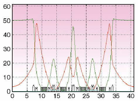
- Since the undulator radiation has to be collimated by some slits to minimise the heat load on the optical components of the beamlines, the horizontal electron beam emittance is optimised to provide minimum beam sizes of the radiation on the slits. A value in the 0.1 to 0.3 nm range appears to be a good compromise to minimise the transmitted power without reducing the flux. Achromats with more bending magnets than operational lattices such as the Double Bend Achromat or the Triple Bend Achromat are necessary to fulfil the emittance / number of cells requirement. An example of structure with 4 dipoles per achromat is shown in Figure 133. The use of damping wigglers as a means of reducing the emittance has been withdrawn since the detrimental effects (unavailable straight sections, power to be handled, ID technology,) exceed by far the added value (a reduction in emittance by a factor of 2).
- Given the high heat load on absorbers, an initial stored current of 0.5 A looks a realistic figure. In order to minimise the multibunch coupled bunch instabilities, the use of strongly HOM damped cavities is mandatory. A scenario with 6 SOLEIL-type super-conducting cavities is being considered.
 |
Fig. 133: Optical functions of a lattice providing a 0.3 nm emittance at 7 GeV.
|
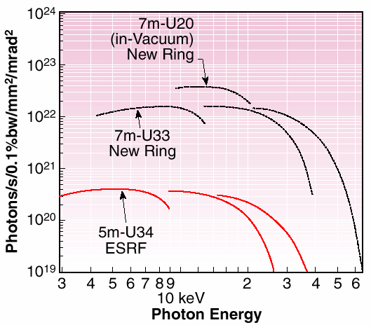
The expected brilliance is shown in Figure 134. More detailed studies on lattice optimisation to provide large energy acceptance, the design of the vacuum vessel to minimise its impedance to the beam, the layout of the crotch absorbers and the front-ends which will have to handle the tremendous beam power, the means to provide the required beam stability, will be tackled in the forthcoming months.
 |
Fig. 134: Undulator brilliance of the new ring compared to the ESRF best achieved figures.
|


