- Home
- Users & Science
- Scientific Documentation
- ESRF Highlights
- ESRF Highlights 2004
- The X-ray Source
- Global Position Feedback
Global Position Feedback
The closed orbit stabilisation of the ring is performed using a slow and a fast system. The slow system, which includes more than 200 beam position monitors, operates in both the horizontal and vertical plane and corrects the closed orbit every 30 seconds. The slow system is efficient for correcting the orbit drift during current decay. The fast orbit correction system operates in the .1Hz to 150Hz frequency range and corrects beam motion induced by quadrupole and girder vibrations. Beam vibrations at frequencies higher than 150 Hz are typically lower and therefore of less importance to the beamlines. Until 2004, the fast orbit correction was performed on the storage ring by means of a global feedback loop system which damps the vertical orbit distortion all over the storage ring, and by four local feedback systems damping the horizontal orbit distortion only in the ID8, ID14, ID21 and ID24 straight sections.
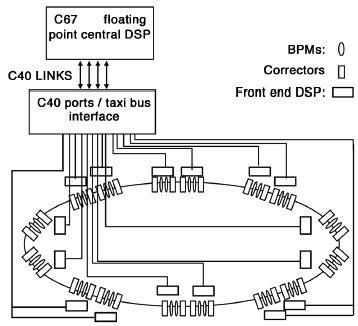
In the early days of operation, the global vertical feedback showed a significantly improved vertical stability of the beam. In 2000, damping pads were fixed to all the quadrupole girders and resulted in a significant damping and reduction of the residual beam oscillations. As a result, the improved stability induced by the vertical global feedback system became marginal. The limitation in the correction come from the noise in the beam position monitor reading and it appears that the only way of further improving the vertical beam stability consists in increasing the number of beam position monitors in the feedback loop. With respect to horizontal stability, the situation has become unsatisfactory with the impossibility to add any new beamlines without generating horizontal position instability. This is due to the imperfect closure at high frequency of the local bumps. Instabilities are generated when more than four local feedback systems are operated at the same time. As a consequence the gain, and therefore the performance, of the feedback loops had to be reduced as more local feedbacks were implemented from one (in 1999) to four (in 2001). The obvious way to improve the stability in all beamlines is to transform the 4 local feedback loops into a single global horizontal feedback loop allowing stabilisation in all beamlines simultaneously. Such an upgraded two-plane global feedback with twice more beam position monitors as compared to the first system was put into operation in 2004. It includes 32 beam position monitors and 24 steerer magnets. The layout is shown in Figure 161.
 |
|
Fig. 161: Layout of the upgraded global feedback system in the storage ring. |
The measured beam stability with and without feedback is summarised in Table 6. The beam position monitors used in the global feedback are located on both extremities of the Insertion Device chambers. It can be clearly seen from Table 6 that the absolute stability achieved is higher in the vertical plane than in the horizontal plane. However, the relative stability (residual motion scaled to the electron beam size) is higher in the horizontal plane.
|
|
|
Table 6: Stabilisation of the residual beam motion obtained with the newly developed global feedback measured in the frequency range 0.1 to 200 Hz. The range of rms motion shown in the table corresponds to measurements made on several beam position monitors. The steerers, the BPMs and the source of noise are not uniformly located along the ring circumference, which explains the difference or residual rms motion from one beam position monitor to the next. |


