- Home
- Users & Science
- Scientific Documentation
- ESRF Highlights
- ESRF Highlights 2010
- Accelerator and X-ray Source
- Reduction of the vertical emittance
Reduction of the vertical emittance
Third-generation light sources are characterised by low transverse beam emittances. The largest contribution to the vertical emittance comes from undesired vertical dispersion and coupling between the two transverse planes, both originating from small residual magnetic and alignment errors in the storage ring. The interest of coupling correction is three-fold. Firstly, smaller vertical beam sizes (proportional to the square root of the vertical emittance) allow the reduction of the magnetic gap of insertion devices, making it possible to reach higher magnetic fields, and hence photon flux. Secondly, any reduction of the vertical emittance induces higher photon brilliance from the undulators. Thirdly, large horizontal oscillations during injection experienced by the incoming off-axis beamlet would have limited impact on the vertical clearance, hence reducing the radiation dose during injection.
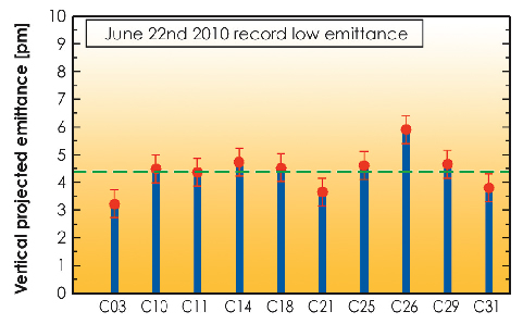
During 2010, a new correction algorithm developed at the ESRF was successfully implemented. It was possible to correct coupling and vertical dispersion of the bare machine (i.e. at open ID gaps) with the available 32 corrector skew quadrupoles at unprecedented levels, yielding the lowest vertical emittance ever measured at the ESRF, 4.4 ± 0.7 pm (see Figure 154).
 |
|
Fig. 154: Record vertical emittance at open ID gaps measured using the 10 in-air X-ray monitors located around the ring circumference. |
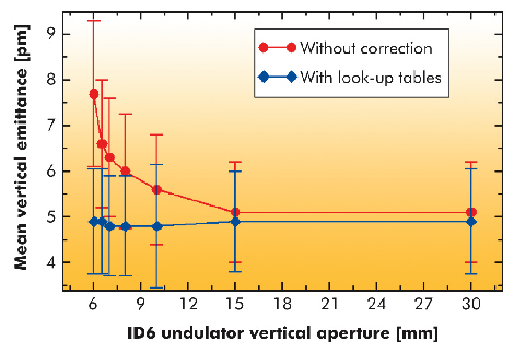
With closed (fixed) gaps, values between 5 and 7 pm are routinely achieved. To preserve low emittance against ID gap movements, two additional correction schemes were also conceived. The first consists of cabling the two steerers placed at the ends of a few straight sections as skew quadrupoles and to power them in order to compensate ID gap-dependent skew quadrupole errors by means of look-up tables. The red curve of Figure 155 shows the vertical emittance growth when the gap of the in-vacuum ID06 undulator decreases, while the blue curve demonstrates how effective this correction can be in preserving low emittance. This correction scheme has been applied to a single undulator segment and will be applied to a few more in 2011. Fortunately, the majority of the 70 ID segments in operation produce negligible residual coupling at all gap values. A further development was a separate coupling feedback to modulate the power of the 32 correctors in such a way as to correct the nearest coupling resonance in the tune diagram.
 |
|
Fig. 155: Vertical emittance measured with and without coupling look-up tables. |
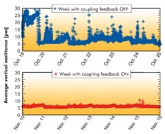
Figure 156 shows a comparison between two USM weeks with and without the coupling feedback: while large variations between 6 and 30 pm are observed in the later case, a rather stable vertical emittance between 6 and 7 pm was achieved during that week when the coupling feedback was on.
 |
|
Fig. 156: Comparison between the vertical emittance measured during an USM week without (top) and with (bottom) coupling feedback correcting the closest sum resonance in the tune diagram. |
In the wake of these successful results, a study was carried out to assess whether a larger number of corrector skew quadrupoles might lead to even smaller emittance. Simulations indicate that 2 pm may be achieved with 32 additional correctors. The latter are already installed (but not yet used) in the storage ring. During 2011 it is foreseen to power them and to include them in the coupling correction.
References
A. Franchi, L. Farvacque, J. Chavanne, F. Ewald, B. Nash and K. Scheidt, submitted to Physical Review Special Topics in Accelerators and Beams.


