- Home
- Users & Science
- Scientific Documentation
- ESRF Highlights
- ESRF Highlights 2013
- Structure of materials
- HEMD resolves different deformation modes in highly nanotwinned Cu
HEMD resolves different deformation modes in highly nanotwinned Cu
Mechanical engineers dream of optimum materials with the highest strength and formability. Reducing the grain size of a metal down to the nanoscale (< 100 nm) is a common strengthening approach, but typically accompanying the strength is a decrease in the metal’s ability to deform plastically (i.e. ductility), which is critical for many applications. A recent alternative approach to this problem is to introduce high densities of nanoscale growth twins into the metal. The boundaries separating the twins (i.e. twin boundaries) act similarly to normal grain boundaries in strengthening the material, but the symmetry allows dislocations, the main carriers of plastic deformation, to travel across or along the boundaries, thus maintaining some ductility. Unfortunately, the overall deformation behaviour of the unique microstructure of highly nanotwinned metals is not yet fully understood.
 |
|
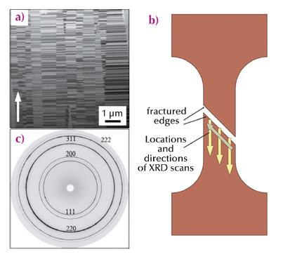
Fig. 120: (a) FIB micrograph of the as-prepared microstructure. (b) Schematic of the scan locations. (c) Diffraction pattern for the as-prepared sample. |
We have already shown that columnar grained highly nanotwinned Cu (shown in Figure 120a) tensile tested at room temperature (RT) and 77 K is deformed primarily through localised shear bands [1,2], which was perplexing as this is not typical for pure Cu. In addition, increases in both strength and elongation-to-failure (i.e. “ductility”) were observed in the sample tested at 77 K. However, the development of the shear bands and their exact role in the deformation behaviour, in particular the enhanced strain, was unclear.
The deformation behaviour and the evolution of the microstructure of nanocrystalline bulk metals during deformation can be followed using high energy microdiffraction (HEMD) at beamline ID15A [3]. The microstructure within nanotwinned Cu specimens was investigated after mechanical testing using a microfocussed, monochromatic high energy X-ray beam (beam size: 8 µm x 20 µm, energy: 69.7 keV). The relatively small beam size permitted the microstructure to be probed locally, and good statistics were obtained since the beam transmits the entire sample. Diffraction patterns comprising several complete Debye-Scherrer rings were obtained using an area detector (165 mm MAR CCD) and were taken every 20-30 µm along and across the shear bands and fractured edges (shown schematically in Figure 120b). For reference, the diffraction pattern of the as-prepared microstructure can be found in Figure 120c. In addition, cross-sectional focused ion beam (FIB) micrographs were prepared at similar locations to directly compare the diffraction patterns with the actual microstructure.
 |
|
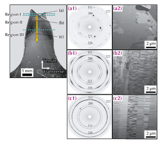
Fig. 121: Nanotwinned Cu gauge section (one half is shown) tensile tested at 77 K. Representative microfocus X-ray diffraction patterns [(a1)-(c1)] and cross-sectional FIB micrographs [(a2)-(c2)] obtained at (a) 50 µm, (b) 700 µm, and (c) 2 mm from the fracture edge. |
Figure 121 shows an optical micrograph, diffraction patterns, and FIB micrographs of one half of the fractured dogbone sample tested at 77 K (arrow represents the scan direction in this case). The results can be separated into three distinct regions with increasing distance d from the fracture edge: d < 120 µm (Region I), 120 µm < d < 1550 µm (Region II), and d > 1550 µm (Region III), where changes in the diffraction patterns correspond to the visible deformation in the sample (specifically, the areas of fracture, shear bands, and outside major deformation). In region I, the diffraction patterns display only individual spots without any observable texture, indicating a severely coarsened material, which is confirmed in the accompanying FIB micrograph. In Region II, a texture is observed consisting of six-fold symmetries with maxima intensities for (111), (200), (311), and (222) reflections in the tensile direction and minima in intensity for the (220) reflection. This texture typically corresponds to dislocation-mediated plasticity and, in this case, is most likely formed by rotation of the columnar grains into directions of preferred slip. Region III shows diffraction patterns and a microstructure very similar to the undeformed as-prepared case. The sample tested at RT developed the same texture within the shear banded region; however, the texture was much more localised and, intriguingly, no coarsening of the microstructure at the fracture edge was found.
This space-resolved high-energy microdiffraction study performed on the tensile tested nanotwinned Cu samples allowed the deformation mechanisms and shear band formation to be explored. The texture in the shear-banded areas identified dislocation-mediated plasticity as the governing deformation process; additionally, the data from the 77K samples allowed the formulation of several theories regarding the apparent increased ductility due to the development of multiple shear bands. This information will contribute to the overall knowledge of nanotwinned metals and their potential use in high strength applications.
Principal publication and authors
T.A. Furnish (a), J. Lohmiller (b), P.A. Gruber (b), T.W. Barbee, Jr. (c) and A.M. Hodge (a), Applied Physics Letters 103, 011904 (2013).
(a) Department of Herospace and Mechanic Engineering, University of Southern California (USA)
(b) Institute for Applied Materials, Karlsruhe Institute of Technology (Germany)
(c) Physical and Life Sciences, Lawrence Livermore National Laboratory (USA)
References
[1] A.M. Hodge, Y.M. Wang and T.W. Barbee Jr., Scripta Mater. 59, 163-166 (2008).
[2] A.M. Hodge, T.A. Furnish, A.A. Navid and T.W. Barbee Jr., Scripta Mater. 65, 1006-1009 (2011).
[3] J. Lohmiller, M. Grewer, C. Braun, A. Kobler, C. Kübel, K. Schüler, V. Honkimäki, H. Hahn, O. Kraft, R. Birringer and P.A. Gruber, Acta Mater. 65, 295-307 (2014).


