- Home
- Users & Science
- Scientific Documentation
- ESRF Highlights
- ESRF Highlights 2017
- Accelerator and Source
Accelerator and Source
The Accelerator and Source Division (ASD) is in charge of the production of synchrotron light from the ESRF’s 6 GeV storage ring. Much of the division’s development work in 2017 has been focused on the ESRF-EBS, and major progress has been made in procurement and assembly, with the arrival of many more components on site and the construction of ESRF 01 and 02 A and B, as detailed in the Status of the EBS section of this report (see page 8). Despite the challenges faced by the increased workload of the project, the division has also continued to ensure excellent machine availability and reliability throughout 2017, including running preventative maintenance campaigns to replace ageing equipment, developing new diagnostics devices, and installing a new ramped injection power supply (RIPS) for the booster.
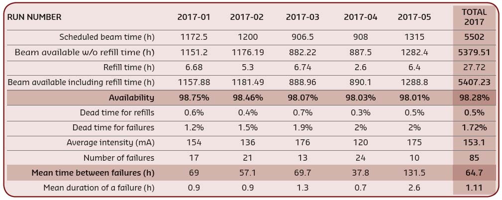
As a result of these efforts, the operation statistics for 2017 are very positive. A total of 5407 hours of beam was delivered out of 5502 scheduled hours, representing an availability of 98.28% and coming very close to the ESRF’s all-time record (99.11%). The Mean Time Between Failures (MTBF) was high, at an average of 64.7 hours. More information on the main parameters of the storage ring can be found on page 167.
In May 2017, refill in top-up mode was put into operation, providing better beam stability, low vertical emittance in all filling modes and a nearly constant beam current. The implementation followed several years of upgrades and modifications to the machine, including, in 2016, a new timing sequence, the development of cleaning in the booster and the start of commissioning of the RIPS. Feedback from the beamlines is extremely positive and the new power supply will provide a crucial back-up in case of failure as well as help to reduce energy consumption at the ESRF.
This year’s achievements would not have been possible without the dedication of the ASD staff and the continuous support of the other ESRF divisions. May this continue in 2018 as we face the challenges of the assembly phase of the ESRF-EBS while simultaneously ensuring optimal operating conditions for our users.
P. Raimondi
Summary of accelerator operation
With one year to go before the dismantling of the storage ring, 2017 has been undoubtedly the year of highs and lows. The highs include several long weeks of deliveries, especially in top-up mode, and the lows were due to some long or repetitive failures, particularly during the final trimester of the year.
In 2017, 5407 hours of beam were delivered out of 5502 scheduled hours. This resulted in an availability of 98.28%, and a MTBF of 64.7 hours, mainly dominated by a few long-lasting failures.
The longest beam interruption lasted more than 12 hours and occurred during the last run of the year, when a faulty valve in the water cooling system on BM20 allowed compressed air to enter the water, meaning the water network had to be switched off. This failure did not actually prevent the operation of the machine as the beam was kept stored, but the beamlines could not operate since their water network was switched off.
The second longest failure occurred the following week when a series of radio frequency arcs prevented a refill. RF experts intervened to inspect the waveguides in question and discovered severe permanent damage on some parts. Several waveguide parts were thus immediately replaced.
The third longest failure, lasting six hours, also occurred in October when the circuit breaker of a full zone of the technical gallery tripped during the night, switching off all electronic devices in this area (including vacuum controllers, gauges, etc.). Several side effects prevented an immediate restart and experts had to intervene during the night to be able to switch the beam back on.
Problems with the kickers in the injection system also caused two separate weeks characterised by failures. The first took place in May and was due to a faulty thyratron, causing 10 beam interruptions. The second, in September, resulted in 15 trips and was caused by an erratic side-effect of the synchronisation of the injection kickers when the injection rate was switched from 10 Hz to 4 Hz after the commissioning of the new booster ramped injection power supply (RIPS). Although the long-term solution is to redesign the associated software, a temporary solution has been implemented to fix this issue.
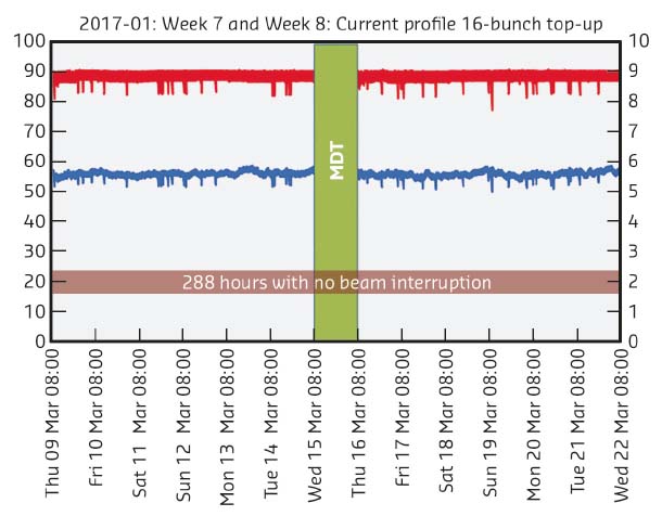
Aside from this, the injectors have proved their excellent reliability: more than 4000 refills took place in all modes over the year (95% of these refills were done in top-up mode). Only 3% of the refills were skipped due to minor injector problems that could be reset straight away. Figure 157 illustrates the excellent rate of top-up delivery during the first run of 2017.
 |
|
Fig. 157: Two weeks of delivery in top-up mode without a single failure. |
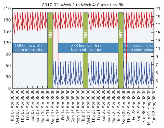
This steady injector reliability also induced several long periods of deliveries without failures during the non-top-up periods, as illustrated in Figure 158 during the second run of 2017.
 |
|
Fig. 158: Three long periods of delivery over a four-week period. |
A significant improvement was made in May 2017 when the new RIPS was put into operation, replacing the former booster magnet power supply system, BPSS. Among many advantages, the RIPS system does not depend upon external temperature, making it much more stable and reproducible for the electron cleaning procedure that is carried out in the booster.
It is also worth noting that during machine operation in 2017 many activities were being performed in parallel, in preparation for the EBS project. Examples include:
• CV 5000 vacuum vessel conditioning in the storage ring and cell 14
• DC-DC power supply cabling work along the technical gallery
• Installation of additional plates under some equipment in the booster in view of the circumference reduction
• Installation of a liquid nitrogen loop in the technical gallery for the cryogenic cooling of in-vacuum devices
A summary of storage ring operation in 2017 is presented in Table 3.
 |
|
Table 3: Overview of storage ring operation in 2017. |
Filling patterns
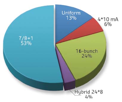
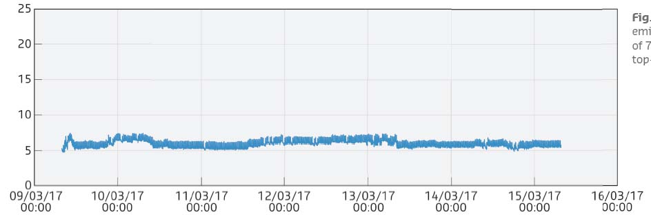
The distribution of the modes did not change significantly compared to 2016, with a large preference for the 7/8 + 1 filling mode (see Figure 159). Today, all 4*10 mA and 16-bunch deliveries are carried out in top-up mode, with a refill every 20 minutes, allowing a very small and permanent vertical emittance in the range of 7 pm.rad, as shown in Figure 160. Thanks to a lot of work accomplished to minimise the disturbance during the top-up refills and to make it faster, most users declared that the refill time is now an almost or even fully transparent process.
 |
|
Fig. 159: Distribution of the various filling modes in 2017. |
 |
|
Fig. 160: Vertical emittance in the range of 7 pm.rad during top-up mode. |
Progress of the top-up project
Back in April 2016, injection in top-up mode was officially launched to users, and throughout 2017 it has been fully operational in 16- and 4-bunch modes. The new mode sees the accelerators refilled with electrons every 20 minutes rather than every four to 12 hours. This results in a much higher integrated current over a 24-hour period, meaning more photons for the users and better beam stability due to smaller current variations. It also means a low vertical emittance in all filling modes. Previously, the vertical emittance would be artificially increased in some modes in order to increase the lifetime, but the nearly constant beam current provided by top-up mode means that the emittance – and the resulting brilliance and resolution for users – no longer has to be sacrificed. The top-up procedure is now well established, the sequencer fully operational, and the injection disturbance has been significantly reduced.
Top-up operation was further improved in 2017 with the installation of the new 4Hz RIPS for the booster. The switch over from the BPSS to the new RIPS system took place following the May shutdown. The switch has provided the ESRF with a crucial back-up power supply in case of failure, and has reduced the energy consumption for injection, avoiding lengthy start-up warming.
 |
|
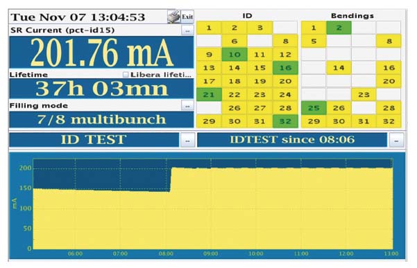
Fig. 161: The control room synopsis display during tests of top-up operation in 7/8+1 filling mode in November 2017. |
In view of the implementation of top-up in 7/8+1 filling mode, foreseen for 2018, tests were performed in collaboration with users in November 2017 (Figure 161). The tests evaluated the impact of injection on the more demanding beamlines, using coherence. Depending on the results, further improvements could still be envisaged in order to reduce perturbation.
Reduction of beam disturbance at injection
In the context of the top-up project, the disturbance of the beam trajectory during injection has been drastically reduced thanks to the improvement of the injection kicker system and the addition of several active disturbance cancellation systems.
The most severe perturbation is caused by the presence of sextupole magnets inside the injection bump generated during the 2.8 ms injection revolution; these sextupoles apply an extra parasitic kick to the beam during the rise and fall of the bump amplitude. This parasitic kick has been reduced to one third of its initial amplitude by the addition of conductive shims inside the kicker magnets, introducing a non-linear field component to the normal dipole field of the kickers that partially cancels the parasitic effect of the sextupoles. The remaining parasitic horizontal kick is further reduced by the application of a set of correction kicks produced by an auxiliary kicker able to produce arbitrary shape kicks matching the residual perturbation. A vertical parasitic kick is also present, caused by some misaligment of the injection kickers. This vertical kick has been reduced by the addition of skew quadrupole magnets inside the bump and a vertical correction kicker driven by an arbitrary shape correction signal generator.
The septum magnets fired at injection also affect the stored electron beam. The fast orbit feedback has been modified by implementing a feed-forward feature. This feedforward, triggered at each injection, generates a set of correction kicks to cancel the orbit distortion.
Appendix 1: Beam parameters of the storage ring
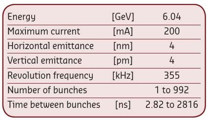
Table 4 presents a summary of the characteristics of the storage ring electron beam in optimal conditions.
 |
|
Table 4: Principal characteristics of the electron beam. |
Table 5 gives the main optic functions, electron beam sizes and divergences at various source points. For insertion device source points, the beta functions, dispersion, sizes and divergences are calculated in the middle of the straight section. For bending magnets, two representative source points have been selected for each type of magnet (even or odd cell number), corresponding to magnetic fields of 0.4 T and 0.85 T. These points differ by the observation angles, of respectively 3 and 9 mrad from the entrance of the magnet.
 |
|
Table 5: Beta functions, dispersion, rms beam size and divergence at the various source points. |
Electron beam profiles are Gaussian and the size and divergence are presented in terms of rms values. The associated full width at half maximum sizes and divergences are 2.35 times higher. Horizontal electron beam sizes and divergences are given for the multibunch filling modes and apply to almost all filling patterns, except when the current per bunch is larger than 4.5 mA, for which a slightly larger size and divergence are attained because of the increased energy spread of the electron beam.
Vertical electron beam sizes and divergences are given for a vertical emittance of 4 pm, which is now the optimal condition for 2 x 1/3 and 7/8+1 filling modes. The vertical sizes and divergences are about 1.4 times larger in uniform filling mode (due to ion effects, which are partially corrected by the use of a vertical bunch-by-bunch feedback).
The lifetime, bunch length and energy spread mainly depend on the filling pattern. These are given in Table 6 for a few representative patterns. Note that in 16-bunch and 4-bunch filling patterns, the energy spread and bunch length decay with the current (the value indicated in the table corresponds to the maximum current). The bunch lengths are given for the usual radiofrequency accelerating voltage of 9 MV (8 MV for 16-bunch and 4-bunch).
 |
|
Table 6: Current, lifetime, bunch length and energy spread for a selection of filling modes. |


