- Home
- Users & Science
- Find a beamline
- Electronic structure, magnetism and dynamics
- ID28 - Inelastic Scattering II
- Beamline Layout
- Optical Hutch 3
- High energy resolution backscattering monochromator
High energy resolution backscattering monochromator
The main monochromator consists of a flat perfect single crystal, operating at a Bragg angle of 89.98º and utilising the silicon (n,n,n,) reflection orders. This close-to-exact-backscattering configuration insures that the spectral angular acceptance, the so-called Darwin width, is larger than the x-ray beam divergence, and therefore that all the photons within the desired energy bandwidth are transmitted. The crystal is temperature controlled in the mK region by a high precision platinum 100Ω (Pt100) thermometer bridge in closed-loop operation with a PID controlled heater unit. The complete electronic unit was purchased from Automatic Systems Laboratory (Milton Keynes, England).
The Energy scans are performed by varying the temperature of the monochromator and keeping the temperature of the analyzer fixed.
The performances of the very high energy resolution monochromator are summarised in Table below :
| Reflection | Energy [keV] | δ E [meV] | δ T [meK] | δ E/E | Flux [photons/sec] |
|---|---|---|---|---|---|
| Si(7,7,7) | 13.840 | 5.30 | 150 | 3.8.10-7 | 10.5.1010 |
| Si(8,8,8) | 15.817 | 4.40 | 109 | 2.8.10-7 | 9.00.1010 |
| Si(9,9,9) | 17.794 | 2.20 | 48 | 1.2.10-7 | 2.70.1010 |
| Si(11,11,11) | 21.747 | 0.83 | 15 | 4.7.10-8 | 6.60.109 |
| Si(12,12,12) | 23.725 | 0.73 | 12 | 3.1.10-8 | 5.85.109 |
| Si(13,13,13) | 25.704 | 0.50 | 7.6 | 1.9.10-8 | 1.47.109 |
Energy indicate the photon incident energy; ![]() E is the energy resolution;
E is the energy resolution; ![]() T is the equivalent of
T is the equivalent of ![]() E in mK;
E in mK; ![]() E/E is the resolving power; Photon Flux measured behind the silicon (n,n,n) high energy resolution backscattering monochromator. Experimental conditions: two 1.6 m U32 undulators; ring current: 200 mA; primary slits aperture: 1.6 mm (horizontal) x 0.7 mm (vertical); secondary slits aperture: 2.4 mm (horizontal) x 1.0 mm (vertical).
E/E is the resolving power; Photon Flux measured behind the silicon (n,n,n) high energy resolution backscattering monochromator. Experimental conditions: two 1.6 m U32 undulators; ring current: 200 mA; primary slits aperture: 1.6 mm (horizontal) x 0.7 mm (vertical); secondary slits aperture: 2.4 mm (horizontal) x 1.0 mm (vertical).
 |
 |
|
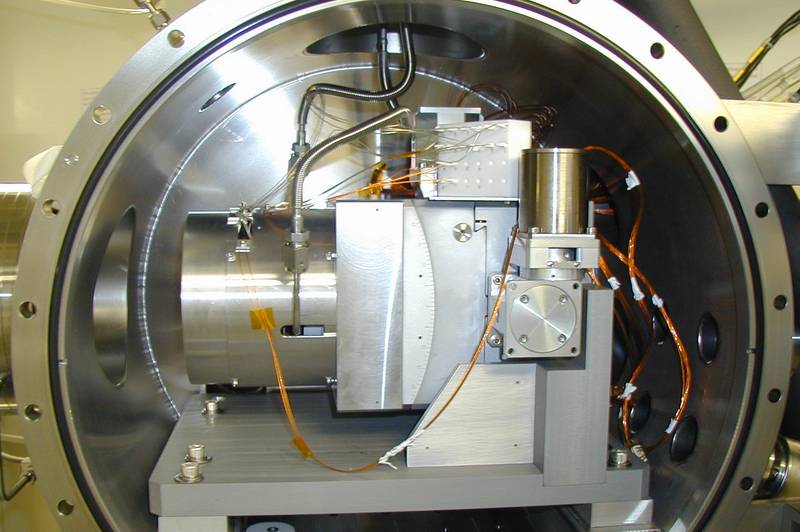
Picture 1 : Vertical main mono setup. |
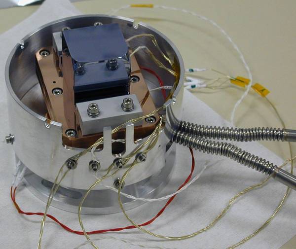
Picture 2 : Main mono crystal and temperature control assembly . |
Main mono (horizontal setup)
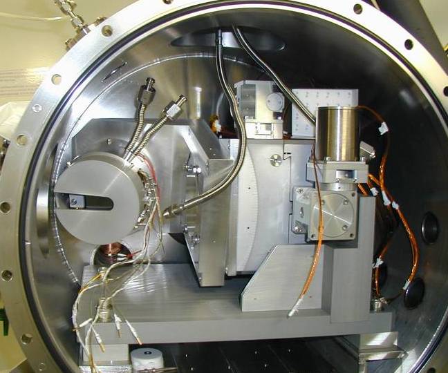
Despite the premonochromatisation of the undulator beam by the silicon (1 1 1) channelcut crystal, the power of the x-ray beam impinging on the main monochromator is in the order of several 10 mW. The corresponding power density (for a symmetric main monochromator) is enough to create a temperature gradient within the diffracting volume of the crystal, and consequently leads to a broadening of the resolution function at the two highest employed reflection orders. In order to circumvent this problem, asymmetrically cut crystals with asymmetry angles a of 76 – 85 degrees are used. The resulting reduction in power density ensures the conservation of the optimum energy resolution. If the crystal is cut in such a fashion that the surface normal and the reciprocal lattice vector both lie in the vertical scattering plane, the apparent vertical source size, and consequently the focal spot size, is increased due to a refraction effect. For experiments, which need a very small focal size, an alternative configuration is utilised, in which the monochromator is mounted such that the surface normal and the reciprocal lattice vector are comprised in an almost horizontal plane. In this geometry the undesired source size increase is suppressed.

Picture 3 : horizontal main mono setup


