- Home
- Users & Science
- Find a beamline
- Electronic structure, magnetism and dynamics
- ID28 - Inelastic Scattering II
- Temperature Control System
Temperature Control System
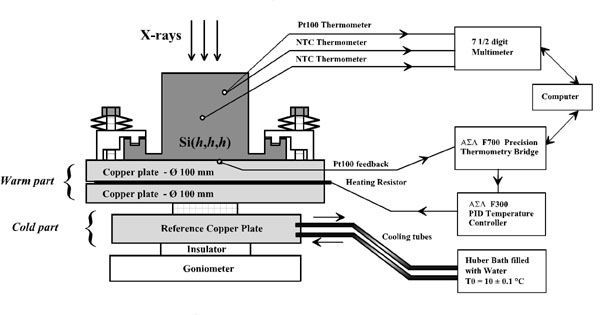
The monochromator and analyzer crystals have a very similar temperature control assembly. It is shown schematically in Figure 1. The core of the assembly consists of a cold part and of a warm part. The cold part is basically a copper plate which is water cooled by a closed thermostat circuit capable to stabilise the temperature with a precision of ± 0.1 K. The warm part consists of two copper plates in which is sandwiched the heating resistor. The monochromator (analyzer) crystal is fixed on top of the warm part by special clamps to avoid undesired stress and strain. The cold and warm parts are in thermal contact each other. This contact should be good enough to allow to evacuate the power of the heater, necessary to have a fast response to a new temperature set point. This contact, however, must not be too good, otherwise the heater has to work at a higher power, and this may create undesired thermal gradients in the assembly and eventually in the crystal. The whole system is thermally isolated from the goniometer head and kept in high vacuum. A further Aluminium screen avoids perturbations from heat radiation coming from the motors of the goniometer and from the walls of the vacuum chamber.
The temperature control system consists of a feedback loop composed of a very high Precision Thermometry Bridge reading a 100 ![]() platinum resistance (Pt100) and a (Proportional Integrative Derivative) PID controller connected to the heating resistor. The Thermometry Bridge measures the ratio of two, four terminal resistors, Rt and Rs. The internal reference resistor Rs is mounted in a temperature controlled oven and it has a value of 100 ohms ± 50 ppm with a short term stability better that ± 1 ppm. The Thermometry Bridge is computer controlled and, in its high-sensitivity mode, allows to control the temperature to a minimum step of 0.25 mK.
platinum resistance (Pt100) and a (Proportional Integrative Derivative) PID controller connected to the heating resistor. The Thermometry Bridge measures the ratio of two, four terminal resistors, Rt and Rs. The internal reference resistor Rs is mounted in a temperature controlled oven and it has a value of 100 ohms ± 50 ppm with a short term stability better that ± 1 ppm. The Thermometry Bridge is computer controlled and, in its high-sensitivity mode, allows to control the temperature to a minimum step of 0.25 mK.
The feedback Pt100 resistance, connected to the Bridge, is located in a small hole on the upper copper plate not too far away from the heating resistor (see Figure 1). The temperature variations in the monochromator crystal are continuously monitored with further three thermometers: 1) one Pt100 resistance plus one 11 k![]() NTC (Negative Thermal Coefficient) resistance are placed together in a small hole drilled in the monochromator crystal at approximately 1 cm from the backscattering surface; 2) one 11 k
NTC (Negative Thermal Coefficient) resistance are placed together in a small hole drilled in the monochromator crystal at approximately 1 cm from the backscattering surface; 2) one 11 k![]() NTC resistance is placed on the monochromator crystal’s surface.
NTC resistance is placed on the monochromator crystal’s surface.
The Pt100 and the NTC thermometers are particularly suited to our applications because they have small dimensions, react very fast to the temperature variations, can resolve temperature steps smaller than 1/1000 of degree, and have a good thermal stability around room temperature. The thermometers are monitored utilising a 7½ digit multimeter interfaced with the computer. The temperature stability of the monochromator crystal is better than ± 1 mK per hour. This value is strongly related to the temperature stability of the monochromator hutch that normally is of the order of ± 0.2 K.


