ID10EH1 Overview
Introduction
EH1 experimental hutch of the ID10 beamline hosts a multi-purpose instrument for the study of liquid and solid interfaces, combining grazing-incidence diffraction (GID), x-ray reflectivity (XRR), and grazing-incidence small-angle scattering (GISAXS) techniques in a single instrument. Scattering experiments can be performed in both horizontal and in vertical scattering geometry. High-resolution studies are possible in both scattering geometries via the use of analyzer crystal stages in different orientations. A speciality of ID10-EH1 is the study of organic thin films on solid or liquid and fluid surfaces. With the techniques of GID, XRR and GISAXS, length scales from sub-nm to 100 nm, in some cases even up to 1000 nm, can be explored. This allows to investigate self-organization processes at surfaces, interfaces and in thin films.
Beamline Overview
 |
|
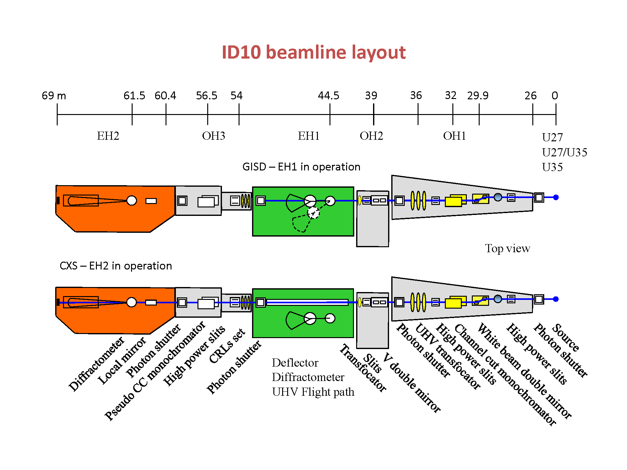
Fig. 1: Schematic layout of the ID10 beamline. |
Click here to get detailed drawing of the Optics hutch (pdf format)
Click here to get detailed drawing of the Experimental hutch (pdf format)
EH1 is one of two experimental complexes of ID10 stations working in the time-sharing mode.
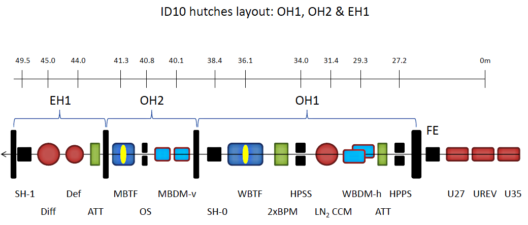
The schematic layout of the ID10 beamline is shown in Figure 1. The front end (FE), located 26 m from the insertion devices (ID) interfaces the beamline to the storage ring and contains the main beam shutter and a diamond window (300 µm). The first optics hutch (OH1) has common elements that can be used by both ID10 stations and all of them are whitebeam compatible. The white beam from the undulators enters the optics hutch about 27m downstream of the source point, where it is defined by a pair of high-power primary slits (HPPS). The first key optical component of the new ID10 beamline is the horizontally reflecting white beam double mirror (WBDM) located 3m downstream from the HPPS. The horizontal reflection provides stability and better coherence preservation. To have flexibility in the band pass filtering up to 30keV the double mirror has three reflecting surfaces on a silicon body: a central stripe with bare silicon (Si) and two lateral stripes coated with Platinum (Pt) and Palladium (Pd). Two meters downstream from the WBDM there is the UHV vessel containing the two liquid nitrogen cooled channel-cut Si monochromators (CCM) serving the ID10-SI station and optionally ID10-CS station. CCMs operate at Si(111) and Si(311) symmetric Bragg reflections. CCM Si(111) provide X-rays in the energy range 7-24 keV. CCM Si(311) helps to reach X-rays in the energy range 14-30 keV. A secondary high-power slit unit (HPSS) is located downstream to the CCM at 34m from the source. It is used in combination with the HPPS and the ternary high-power slits in OH3 (HPTS) to define a virtual horizontal source for ID10-CS. Two beam positin monitors (BPM) for the white and monochromatic beam respectively located right after the HPSS. The last key element of OH1 is the white-beam transfocator (WBTF) which is located at 36m from the source. It is the first optical element focusing the beam for the downstream experimental hutches in the energy range between 7 and 30keV.
 |
|
Fig. 2: Schematic layout of ID10-SI station (distances are from source in m) SH-0 and SH-1 are safety shutters. |
The Optics hutch (OH2) is a continuation of OH1 and is serving exclusively the station ID10-SI. OH2 hutch is only compatible with monochromatic beams. Despite the limited space, three optical elements are installed here: the monochromatic beam double mirror (MBDM), a pair of slits (OS) and the monochromatic beam transfocator (MBTF). The latter is equpped with a set of beryllium compaund refractive lenses (200 micron radius) which can focus the beam to 4 microns on the sanmple position.
The first experimental hutch (EH1) is equipped with an instrument which comprises the beam deflector stage (Def), mainly used for experiments on liquid surfaces and the multi-purpose 2+2 circle diffractometer (Diff) for surface/interface studies in soft- and hard condensed matter systems. Deflector stage rotates the X-ray beam around fixed point on the liquid surface so that the sample does not move in the space. The diffractometer has a two-component detector arm and a combined scattering stage for both horizontal and vertical scattering geometries. The sample position on the diffractometer is at 45 m from the source.
| Name of element | Position, mm |
|---|---|
| HPPS | 27180 |
| WBDM | 29277 |
| LN2 CCM | 31375 |
| HPSS | 34014 |
| WB-Transfocator | 36152 |
| MBDM | 40336 |
| OS (Optics Slit) | 40832 |
| MB-Transfocator | 41346 |
| Deflector (652mm upstream from COR) | 44424 |
| Diffractometer (COR-center of rotation) | 45076 |
The Undulator Source
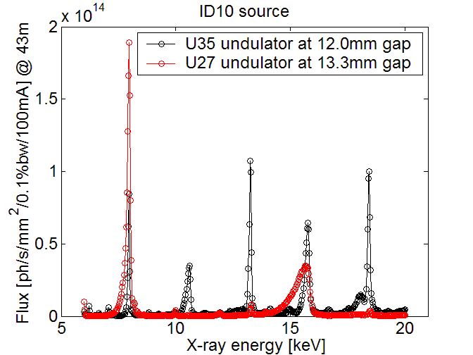
The beamline uses three undulator segments in series: one 27 mm undulator (U27), one 35 mm undulator (U35), and a revolver unit carrying both U27 and U35 undulators. Hence the source consists of either 2xU27+U35 or 2xU35+U27 depending on the energy requirements. All undulators are installed in series in the ID10 high-β straight section. The source size (FWHM) for the 3.9 nm lattice and 1% coupling is 928 µm (horizontal) and 23 µm (vertical). The electron beam divergences are 24 µrad (h) and 9 µrad (v) . The divergence of the photon beam depends on the length of the undulator, the photon energy, the energy spread of the electron beam and the undulator tuning. Typical divergences (FWHM) at 10 keV are 28 µrad (h) and 17 µrad (v) implying a maximum beam size of 1.5 mm (h) x 0.8 mm (v) at CMM (31.4 m from source). The total emitted power from a single undulator is 1.14/2.05 kW (U27/U35 @ 100 mA) and the maximum power density in the central cone at 27 m distance is 66 W/mm2 for both undulators at 100mA ring current. Figure 3 shows undulator spectra taken with a Si monochromator crystal. More details about the UNDULATOR SOURCE
 |
|
Fig. 3: Flux spectra of the ID10 undulators tuned to produce 8 keV photons (U27: 1st harmonic, U35: 3rd harmonic). The spectra were recorded with a Si (111) crystal in symmetric Bragg scattering geometry. |
The White Beam Double Mirror
The white beam double mirror (WBDM) is the first optical element of the ID10 beamline. Its role is essential for the pink beam operation (optionally) and for reducing the heat load on the downstream components. It is a water cooled device with a side cooling scheme that operates under full longitudinal illumination for minimal thermal deformation (minimum thermal bump) and the highest stability. It is compatible with power loads up to 500W. Today the unfiltered maximum power can reach 190W at 200mA. The mechanical design has been developed at the ESRF based on the horizontal reflection geometry. The horizontal reflection provides stability and better coherence preservation, since the reduced transverse coherence length of the high-beta sources in the horizontal plane (5µm at 8keV) renders state-of-art requirements for the wave-front preservation. The ultra-rigid mount designed at ESRF limits the range of the grazing angle from 2.6 to 3.6mrad.
With a fixed gap of 1.6mm between the two mirrors the second mirror is 500mm long to intercept the beam reflected by the first mirror in the entire angular range. To have flexibility in the band pass filtering up to 30keV the standard scheme with three reflecting surfaces on a silicon body has been adopted: a central stripe with bare silicon (Si) and two lateral stripes coated with Platinum (Pt) and Palladium (Pd). The grazing angle of 2.6mrad provides energy cut-offs at ~11keV (Si) and ~23keV (Pd).
Operating in the range between 2.6 and 3.6mrad allows the third harmonic rejection to be better than 10-5 in the energy range 7-12keV and 14-30keV.
The LN2-cooled channel-cut monochromator
Both end stations of ID10 require high monochromaticity, high flux and energy tunability in a wide energy range. The ID10-SI station exploits the full unfiltered beam (1.0x0.5mm2 HxV) from the source for the grazing incidence surface scattering/diffraction techniques in the energy range 7-30 keV. This is accomplished by two ESRF generic Si(111) and Si(311) liquid-nitrogen cooled channel-cut crystals with vertical symmetric Bragg-Bragg scattering mounted in a UHV vessel (CCM - channel cut monochromator).
The Si(111) crystal provides monochromatic beam in the energy range 7-24 keV, the high-resolution Si(311) crystal in the range 14-30 keV. Both crystals sit on a common Bragg rotation and have individual pitch adjustment for compensating the residual internal angle mismatch. To switch between the two monochromators the full vessel can be translated transversally in the horizontal plane as well as in the vertical plane for the height positioning. With all three insertion devices tuned for 8keV radiation and primary slits opened to the maximum aperture 1mm(h.)x0.5mm(v.) the produce power impinging on the monochromator in Bragg position for 8keV with Si(111) is of about 30W/100mA. This heat load does not increase the rocking curve width.
CCM device has a parking position that allows the white and pink beams to pass through into the downstream hutches when necessary.
The White Beam Transfocator (in OH1)
The white-beam transfocator (WBTF) is the first focusing device at ID10 positioned at 36m from the source. It consists of a series of nine pneumatic actuators (with in-out position) mounted in a 1m long UHV vessel carrying a 2n number of Be compound refractive lenses (CRLs) with 300mm radius of curvature. Each individual lens holder is water cooled. The first slot is only a pinhole to limit the power load on the subsequent sets. The 300mm Be CRLs sets in number 2n, n=1,2,4,8,16,32, occupy six slots from slot n.3, while slot n. 2 and the last slot n. 9 carry a linear lens and one 200mm Be CRL, respectively. This last lens focuses 7keV X-rays at the ID10-CS station. This system allows us to adjust the focal spot size from half a millimetre down to a few micrometers in a large energy range in EH1 and EH2 by selecting the appropriate number of lenses (up to 63 lenses).
The Monochromatic Beam Double Mirror
The first optical element in OH2 is the monochromatic beam double mirror (MBDM), a UHV device operating in vertical reflection geometry. It is used to tilt the X-ray beam down to the liquid surface at few milliradians for grazing incidence X-ray photon correlation spectroscopy (GI-XPCS) and GISAXS measurement. Optionally, MBDM can be used for the harmonics rejection in the X-ray spectrum. Each mirror has three stripes with Palladium (Pd), Platinum (Pt) and Silicon (Si) reflecting surfaces. To clean up the beam after the WBTF and MBDM a pair of slits, called the optics slits, have been installed downstream of the double mirror.
Double crystal deflector
Info page is under construction.
 |
|
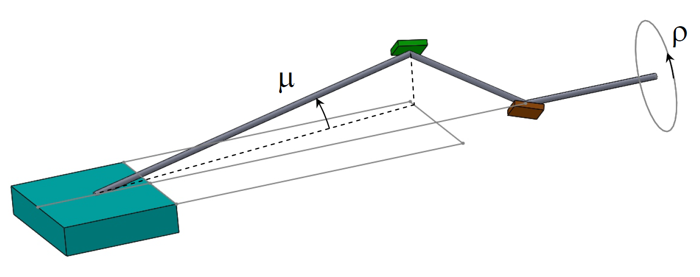
Fig. 4: Double crytstal deflector principle. |
To perform studies on liquid surfaces and interfaces with X-ray scattering, the X-ray beam has to be tilted from the horizontal plane in the desired angular range. For small grazing angles up to 5mrad, as used for grazing-incidence scattering/diffraction, the MBDM of OH2 is suitable. In this case, the beam has no horizontal deviation and the high resolution GISAXS setup on the ID10-EH1 optical axis can be used. This approach allows to reach the Qz scattering vector of no more than 0.04 A-1. For larger Qz values (~ 2.4 A-1), a deflection in larger angles (up to 20 degrees) is needed. The way to reach such high values of grazing angle is the use of Bragg scattering from one or two crystals. The optical device built for this purpose is the X-ray beam deflector, which is located a meter upstream from the sample position.
This single instrument combines a diffractometer with reinforced rotation circles for the detector arm and a double crystal deflector (DCD) with symmetric Bragg reflections. The advantages of the DCD are: 1) only one motor is needed to deflect the beam, which speeds up data acquisition; 2) the incident beam rotates around a fixed point on the sample, so that there is no need to move the liquid surface (no gravity waves). The latter is extremely important for studies on liquid-liquid interfaces.
The DCD principle is based on the Bragg reflection from two crystals, which are rigidly rotated as a single unit around the incident X-ray beam. Such pair of crystals is labelled as Cr-1 and Cr-2 on the Figure. Scattering surfaces of these crystals are faced towards each other and their scattering atomic planes are parallel to each other. In this case, the both normal to the scattering planes lay in the same plane. The Bragg angle of Cr-2 is be bigger than the Bragg angle of the Cr-1. In this case, if initially normal to the scattering planes are in the horizontal plane the doubly reflected X-ray beam is also in the horizontal plane, and it intersects the direction of the initial X-ray beam at a point O. Now if the pair of crystals is rotated as a single unit around the axis (rho) of the initial beam without losing the Bragg condition, the X-ray beam reflected after Cr-2 will move on the cone with its vertex at point O and the opening angle of doubled difference between Bragg angles of two crystals. This provides the X-ray beam tilt at a fixed point O, where the sample has to be placed, and the liquid surface of a sample will not be perturbed, as there is no need to move the sample.
The DCD at ID10-SI operate with Bragg reflection of Si(111) as the first crystal and the Si(220) as the second crystal. The maximum Qz value of this pair of crystals is nearly X-ray energy independent and makes, in our case, 2.4 A-1.
Technical Information
| scientist in charge | Oleg Konovalov tel:+33 (0)4 76 88 27 31, Email |
|||||||
| scientific applications | Undulator beamline for surface diffraction from solids and liquids. /Reflectivity (XRR) , Grazing incidence diffraction (GID), Grazing incidence small angle diffraction (GISAXS), Asymptotic Bragg Diffraction (TRD)/ | |||||||
| source parameters | high β straight section; three undulator segments in series: U27, U35 and a U27/U35 revolver unit. | |||||||
| U27 undulator | U35 undulator | |||||||
| λu | 27 mm | 35 mm | ||||||
| Kmax | 1.27 | 2.34 | ||||||
| field Bmax | 2 T | 2 T | ||||||
| source size | 928 x 23 µm2 (HxV) FWHM | |||||||
| source divergence | 28 x 17 µrad2 (HxV) FWHM @ 10keV | |||||||
| peak brilliance | > 1020 ph s-1mrad-2mm-2 (0.1% bw, 100 mA @ 8 keV) | |||||||
| power | 1.14/2.05 kW @ 100mA ring current (single U27/U35) | |||||||
| power density | 33 W mm-2 (single U27 or U35) @ 27 m distance from source and at 8keV and 100 mA ring current | |||||||
| optics | primary slits | monochromator | WB-Transfocator | |||||
| distance from source: | 27.2 m | 31.4 m | 36.2 m | |||||
| focusing: | white beam and monochromatic beam transfocators | |||||||
| beam size at sample: | < 1 x 0.5 mm2 (HxV) without focusing < 0.03 x 0.1 mm2 (HxV) with focusing |
|||||||
| intrinsic resolution ΔE/E: | 1.4 x 10⁻⁴ Si (111), 2.7 x 10⁻⁵ Si (311) | |||||||
| flux at sample: | ~2.1013 ph/s/mm2 (100 mA @ 8 keV) | |||||||
| detectors | Scintillation counters (Cyberstar) | Ø 10 or 25 mm | ||||||
| Kapton detector (Kapton scatterer + Cyberstar) | Ø 10 mm | |||||||
| Linear position sensitive stripe detector (Mythen 1K, 1mm thick sensor) | 64 x 8 mm2 | |||||||
| PSD - 150mm (Gabriel/EMBL) | 150 x 10 mm2 | |||||||
| analyzer crystals | Si(111) | 170 x 40 mm2 | only in horizontal scattering geometry | |||||
| Ge(111) | 60 x 40 mm2 | symmetric cut | ||||||
| Si(111) | 60 x 40 mm2 | symmetric cut | ||||||
| Si(111) | 60 x 40 mm2 | asymmetric cut, b=10 at 9 keV | ||||||
| Si(111) | 60 x 40 mm2 | asymmetric cut, b=0.1 at 9 keV | ||||||
| beamline control | Linux machine, SPEC control software | |||||||
| auxiliary equipment | beam deflector: Double crystal deflector with Bragg reflections Si(111)+Si(311) or Pt coated Pyrex mirrors; analyser, Soller collimator, temperature controller | |||||||


