- Home
- Users & Science
- Scientific Documentation
- ESRF Highlights
- ESRF Highlights 2005
- X-ray Imaging and Optics
- Phase-contrast X-ray Imaging Combining Free-space Propagation and Bragg Diffraction
Phase-contrast X-ray Imaging Combining Free-space Propagation and Bragg Diffraction
Despite their common origin, X-ray phase contrast imaging techniques have been treated separately in the literature, both in theoretical and experimental studies. In this work, we show that by using a coherent X-ray beam and choosing an appropriate setup, two techniques, namely propagation-based imaging (PB) and analyser-based imaging (AB), can be combined together to produce images showing original features. This technique is referred to hereafter as ‘Hybrid phase contrast Imaging’ (HI).
The propagation-based technique consists in recording the interference pattern produced by choosing one or several sample-to-detector distances. The theoretical description of the technique is based on Fresnel diffraction [1].
The analyser-based technique consists in placing a perfect crystal in Bragg or Laue geometry between the sample and the detector. The crystal acts as a filter for the radiation refracted and scattered inside the object, since it only accepts a narrow range of angles of the incident beam centred at the Bragg angle for the specific energy [2].
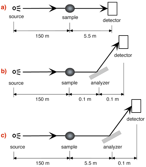
HI is a combination of these two techniques, performed experimentally by analysing the wave transmitted by the sample after propagation in air by means of a perfect crystal. The experimental data were acquired using 25 keV X-rays, a Si(111) analyser crystal (setups shown in Figure 134), and, as pure phase objects (negligible absorption), thin cylindrical polymer fibres (nylon and kevlar wires with diameters of 350 and 200 µm, respectively).
 |
|
Fig. 134: Schematic representation of the configurations used for image acquisition: (a) Propagation-based Imaging; (b) Analyser-based Imaging; (c) Hybrid Imaging. |
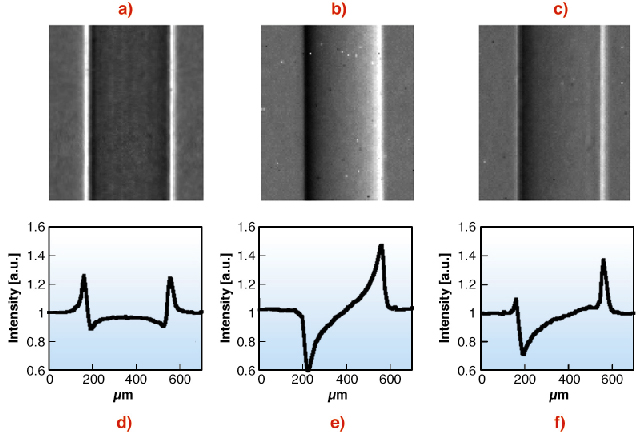
Figure 135 shows some examples of the images and the extracted intensity profiles acquired using the three techniques. The quantitative analysis has been carried out by evaluating the signal-to-noise ratio (SNR).
 |
|
Fig. 135: Images and vertical profiles of the nylon wire: (a,d) PB; (b,e) AI; (c,f) HI. |
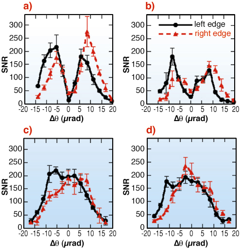
In Figure 136 the SNR versus the angular setting of the analyser is reported, for the two edges of the wires imaged with the AB and the HI techniques. The SNR values for the left and right edge in the PB configuration are respectively 179 ± 30 and 165 ± 12 for the nylon wire and 242 ± 30 and 207 ± 25 for the kevlar wire. The visibility of the two edges, in terms of SNR, changes substantially by varying the angle of the crystal and is mirrored with respect to the axis ![]()
![]() = 0. In AB, this behaviour can be explained by considering the different origin of the signal for the various angular positions. In particular, while at
= 0. In AB, this behaviour can be explained by considering the different origin of the signal for the various angular positions. In particular, while at ![]()
![]() = 0 the signal mainly derives from refraction and the reduction of the scattering component on the image, for the other angular positions it is determined by the analyser alignment with respect to a given direction of the refracted X-rays. Therefore, by rocking the crystal, it is possible to optimise the visibility of the details. At around
= 0 the signal mainly derives from refraction and the reduction of the scattering component on the image, for the other angular positions it is determined by the analyser alignment with respect to a given direction of the refracted X-rays. Therefore, by rocking the crystal, it is possible to optimise the visibility of the details. At around ![]()
![]() = 0 there is a minimum of the derivative of the rocking curve, and then the crystal is less sensitive to X-rays refracted inside the object, determining a low SNR. On the tails of the rocking curve, the low reflectivity increases the image-noise, also reducing the SNR. In the case of the HI technique, the main difference with respect to AB concerns the SNR values around the exact Bragg angle. In fact, while the AB signal is maximum on the shoulders of the rocking curve and it decreases towards
= 0 there is a minimum of the derivative of the rocking curve, and then the crystal is less sensitive to X-rays refracted inside the object, determining a low SNR. On the tails of the rocking curve, the low reflectivity increases the image-noise, also reducing the SNR. In the case of the HI technique, the main difference with respect to AB concerns the SNR values around the exact Bragg angle. In fact, while the AB signal is maximum on the shoulders of the rocking curve and it decreases towards ![]()
![]() = 0, in HI the SNR is high even at this position where it also reaches its maximum values because of the constant presence of the PB contribution.
= 0, in HI the SNR is high even at this position where it also reaches its maximum values because of the constant presence of the PB contribution.
 |
|
Fig. 136: Signal-to noise ratio values of the signal produced by the edges of the two wires as function of the angular position of the analyser for AB ((a) nylon wire, (b) kevlar wire) and HI ((c) nylon wire, (d) kevlar wire) configurations. |
The HI signal combines the propagation and diffraction effects: the PB signal, determined in first approximation by the Laplacian of the phase introduced by the object and by the sample-detector distance, passes through the AB crystal acting like a band-pass filter; thus only some frequencies can reach the detector.
HI images present a weak dependence on the angular positioning of the analyser, reducing the constraints in terms of optical alignment and stability of the crystal, which are critical shortcomings of the AB technique.
In order to fully understand the peculiar characteristics of the HI signal, further theoretical and experimental investigations are required. This technique may find application in several fields already advanced by hard X-ray phase-contrast imaging, producing as high SNR as PB, while bringing the advantages of the higher refraction sensitivity of the AB technique.
References
[1] P. Cloetens, R. Barrett, J. Baruchel, J. Guigay, M. Schlenker, J. Phys. D: Appl. Phys., 29, 133-146 (1996).
[2] A. Bravin, J. Phys. D: Appl. Phys., 36, A24-A29 (2003).
Principal Publication and Authors
P. Coan, E. Pagot, S. Fiedler, P. Cloetens, J. Baruchel, A. Bravin, J. Sync. Rad., 12, 241-245 (2005).
ESRF


