- Home
- Users & Science
- Find a beamline
- Matter at extremes
- ID06 Large Volume Press
- The Large Volume Press
The Large Volume Press
Technical Overview
- Large Volume Press at ID06 is a unique 20 MN (2000 tonf) 4-column device with a modified cubic geometry. The LVP is specified to operate in angle-dispersive mode.
- Main ram is oil pressure driven and controlled to 700 bar (2000 tonf)
- Differential U (upper) and D (lower) rams driven, independently, by oil pressure (1900 bar each, 700 tonf) and controlled on position (automatically coupled for deformation)
- 9-axis motor stage allows translation and rotation of the press during the experiment in order to optimize diffraction data coverage or focus on a specific part of the sample.
- Compression is typically performed in 1- or 2-stage (6/8, 6/6) setup, while 3-stage (6/6/2) is possible as well.
- In a 2-stage mode (6/8, hydrostatic compression) the LVP operates with 32 mm WC, 26 mm, 1” WC, 25 mm WC and 14 mm WC and SD (sintered diamond) second stages on a range of steel and carbide primaries.
- 25/17, 18/11, 14/8, 10/5, 10/4, 7/3, 7/2.5 assemblies with octahedral pressure cells are offered as standard.
- Deformation is performed with cubic pressure cells and 6, 4, 3 mm truncated 1-stage anvils in WC and SD.
- A Drickamer apparatus is available with 3 mm culet.
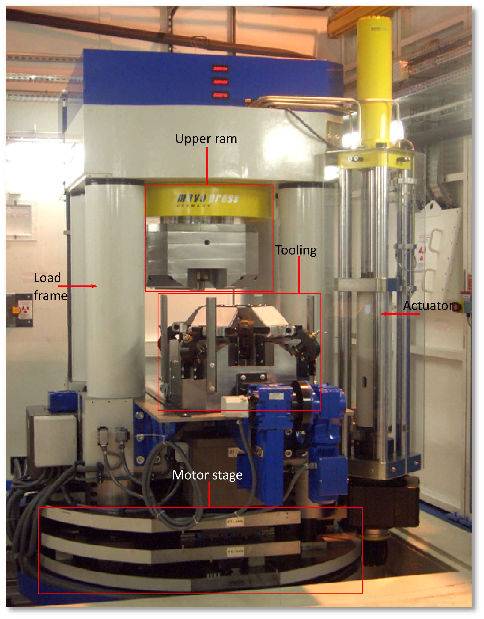
High Pressure Tooling
The chosen tooling is based on a cubic geometry with independent differential rams in up (U) and down (D) positions. Thus the LVP at ID06 is an oversized 2000 ton device (Shimomura et al., 1992) with a deformation capacity, and is considerably larger than the vast majority of D-DIA devices elsewhere (200-400 ton). The latter are primarily used as 1-stage or deformation devices; however, the LVP at ESRF is used as both 1-stage (including deformation) and a 2-stage (6/8, 6/6) device.
The triaxial state of the assembly has been first tested by compressing metal blocks, cycled with setting positions for the HOLD value (relative displacement of the U and D rams along the vertical axis, in mm) that would correct any deviation from cubic geometry at the test load. During this, estimations of the force distribution on U & D relative to the main ram were collected. These confirmed the correlation between force distribution and the return of a cubic metal test piece. Subsequently, for each 2-stage run, either with 25 mm or 32 mm carbides, checks have been made with reference to the force on U & D relative to the main ram: when there is << 1 tonf (<<0.01MN) difference the position of the actual HOLD value are recorded. This way is obtained a long-term, highly populated illustration of the deformation behavior of the device (see Figure 1). With the trends obtained in deviation from cubic geometry relative to press load, we habitually programme continuous HOLD advance (opening of U & D) with load increase at a rate of approximately 33 mm/MN for 32 mm carbides and 31 mm/MN for the 25 mm with steel backing plates.
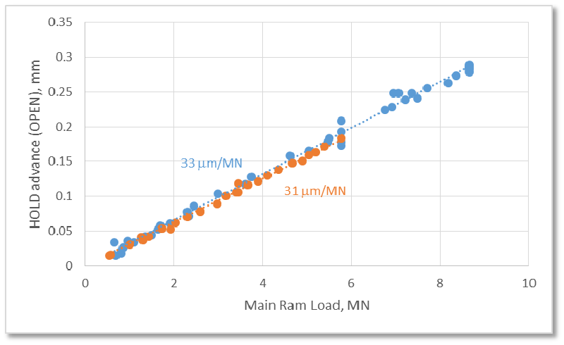
Figure 1. The positions determined for HOLD at given load required to compensate for the difference in effective efficiency (or strength) of compression in the vertical axis compared to the horizontal plane. Relative to no-load initial values for 32 mm carbides (blue) and 25 mm carbides with 7 mm backing plates (orange). Based on, initially, compression tests on test blocks, with confirmation of load repartition through monitoring of U, D and Main Ram pressures at correctly estimated HOLD positions, subsequently added to by monitoring U and D relative to Main Ram load.
In general, application of U & D, as differential rams to enhance triaxiality and force equilibration will improve diffraction data, as samples see stress; using them in the opposite sense to impart differential stress, either in compression or tension, will deform the sample. If this can be carried out at reliable and (laboratory) relevant time-scales then it is a deformation experiment.
Special Design for Angle-Dispersive Data Collection
The LVP device at ID06 is designed to make full use of angle-dispersive geometries for data collection. In practice, this means that orthogonal anvil gaps were opened and primaries include conical cuts for beam access, Figure 2.
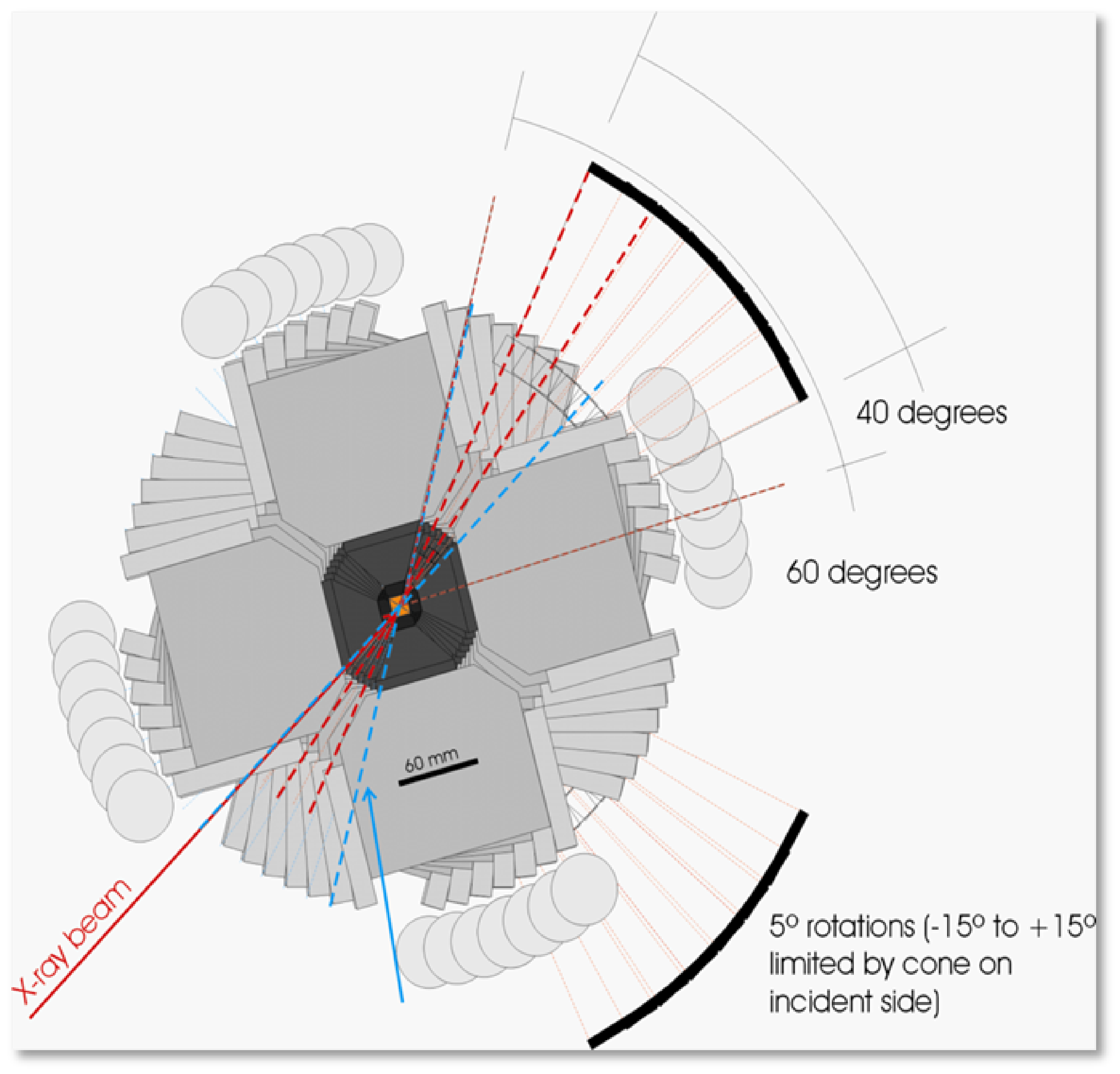
Figure 2. Combining the rotation of the load-frame (+/- 15º at 0º and 90º positions, only achievable through the upstream x-ray cone/slot [blue arrow]), with the extra angular anvil gap available with the use of re-engineered primary anvils should make detection of 2q ranges over 60º in the horizontal plane (where there is the x-ray cone/slit) possible. Considering only the full extent of the vertical solid angle between reengineered anvils should realise coverage of at least 40º (horizontal) x 60º (vertical), about both the 0º and 90º positions. From Crichton, CFT-1534.
In 2-stage 32 mm and 25 mm operation, the horizontal anvil gap between the second stage is the only downstream solid-angle accessible. It is fully open in 2Theta, limited only by the primaries (to reasonable 2Theta). These are then opened with a conical bore on the downstream side to increase such access. This access can be doubled by passing through the similar conical bore on the upstream side and setting the press rotation (w) at an angle sufficient to add these effectively.
In 2-stage 14 mm operation (i.e. SD/cBN anvils) the horizontal extent of the 2Theta is identical to 32, 25 mm, as it is limited by primaries. In replacing the carbide second stage with transparent anvils, there is no secondary stage limitation and the vertical extent is augmented to provide, at any static w position and at no-anvil gap, a minimum of 6º horizontal opening at any vertical position. That is, at any w, +/- 11.5º of pure horizontal 2Theta is accessible through the anvil gap and at any vertical position above a minimum of 6º is obtained.
In 1-stage operation, 2-D data are too limited by primary anvils. However, in this case sintered diamond anvils (Sumitomo) are used on downstream sides (only, typically). With these, at static positions, we now achieve solid-angle detection over a full 360º of azimuth to greater than 10º 2Theta (2 m distance, 6 mm anvils). Rotation of the press (omega) can be effected to augment this (asymmetrically). Current limits on 1-stage opening (with 6 mm anvils) are wedges, rather than the anvils themselves.
partners


European Synchrotron Radiation Facility - 71, avenue des Martyrs, CS 40220, 38043 Grenoble Cedex 9, France.