- Home
- Users & Science
- Find a beamline
- X-ray nanoprobe
- ID13 - Microfocus Beamline
- ID13 Stretching Cells
ID13 Stretching Cells
The use of stretching cells on ID13 is now routine along with other deformation devices (such as bending and shear deformation rigs). A microfocussed beam offers many possibilities for in-situ deformation experiments. These mostly ustilise the scanning set-up which enables the diffraction pattern mapping of materials during stress application. Such in-situ deformation experiments can be performed under either WAXS or SAXS conditions. Studies using WAXS allow investigations into lattice parameter and crystallite orientation changes with stress. Studies using SAXS enable analysis of in-situ crack, craze and void formation during deformation.
Beamline ID13 has a number of in-house stretching devices available for use. It is also possible for users to bring external devices for integration onto the beamline if required. Utilising an in-house device offers several advantages over the integration of an external device:
- No experimental time will be 'wasted' integrating equipment to beamline
- No additional costs or problems associated with shipping and transporting external devices
- Equipment is well tested and therefore failure during an experiment is less likely
Alternatively, there may be some advantages or requirements that necessitate the use of an external user device:
- The specifications can be tailored to experimental requirements
- The user team will already be familiar with equipment use
- The same apparatus can be used for home-institute experiments
If an external deformation device is to be used, the guidelines at the bottom of this page should be noted.
In-House Stretching Cells
There are two types of in-house stretching cell available for use on ID13, a piezo mechanism unit and a linear DC-motor unit. Information on the two types of stretching cell will now be presented in more detail.
Piezo Stretching Cells
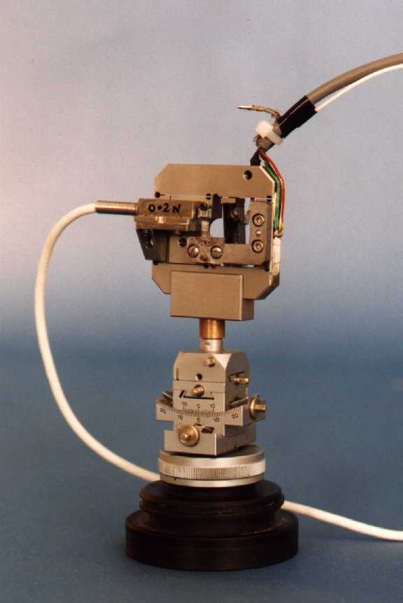
ID13 currently operates two piezo device stretching cells. These offer a greater degree of accuracy than the linear DC motor cell but also have numerous disadvantages. These include a restricted gauge volume, limited travel range and a lower load tolerance.
 |
|
This image shows one of the piezo device stretching cells. Both are mounted on goniometer heads for rapid attachment to the beamline. Control of the piezo unit is achieved by a control box positioned in the control cabin. Samples are mounted directly onto the device using an optical microscope and secured with quick-drying adhesive. |
The first piezo device is specifically for short gauge length specimens. It has a gauge length of approximately 3 mm and a maximum travel range of about 260 microns. The load cell currently mounted to this device has a maximum tolerance of 0.5 N. The second piezo device is designed for longer gauge lengths of approximately 6 mm. The travel range is also greater being in the range of about 300 microns. The load cell currently mounted to this device also has a maximum tolerance of 0.5 N. Both load cells can be exchanged for lower rated models if required (down to 0.1 N).
Linear DC-motor Stretching Cell
There is currently a linear DC-motor stretching cell being designed and built for use on ID13. Although it is currently only under construction, it is expected to be ready for use within the next three months. The linear DC-motor stretching cell will enable large gauge lengths to be tested (up to 100 mm) and higher load levels achieved (0.5 kg maximum). It will also offer a greater range of extension (up to 25 mm) and the possibility of testing pre-prepared samples.
More details on the precise dimensions and specifications of this stretching cell will be made available in due course.
External Stretching Cells
As previously mentioned, it is possible to bring an external deformation rig to ID13 for use in an experiment. In order to ensure that as little experimental time is wasted as possible, the following guidelines should be noted by users.
- Please provide the ID13 technician with an AutoCAD or SolidWorks design of your rig as soon as possible.
- Please discuss any specific requirements you may have with your local contact well in advance of your arrival.
- It is strongly recommended that external rigs are sent to ID13 well in advance of the start of the experiment.
- Note that it may be necessary to recalibrate an external rig on-site following transportation.
- Ensure that the rig conforms with ESRF safety regulations.


