- Home
- Users & Science
- Find a beamline
- Structure of materials
- Instrumentation Facility BM05
- Beamline Guide
- Experimental Hutch 1
- In-situ X-ray scattering and surfacing setup
In-situ X-ray scattering and surfacing setup
Real time in-situ X-ray scattering setup

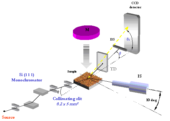
Figure 1: Experimental setup
In the first hutch of the BM05 beamline of the ESRF (at about 40 m from the source), an apparatus (see Figure 1) and a characterization technique have been developed to study the processes of layer growth and ion beam etching in-situ. The technique consists of monitoring simultaneously the specular and diffuse X-ray scattering (XRS) from rough thin films. The description of the surface under investigation is then obtained through the Power Spectral Density of the surface roughness, leading to information on surface topography, root mean square roughness, and correlation between interfaces in the case of thin-films and multilayers. The method provides access to the spatial and temporal evolution of the surface morphology of a thin film during various sample treatments such as sputter growth, ion bombardment, ion beam assisted deposition.

Figure 2: Sketch of the experimental setup
A sketch of the experimental set-up is shown in Fig. 2. The setup integrates two schemes: sample processing and x-ray detection. A vacuum chamber with a base pressure of 10-7 hPa is equipped with a magnetron sputter source for film deposition and an ion source for etching studies. Facing the sputter target the sample is mounted on a rotation stage allowing to adjust its angle with respect to the X-ray beam. Thanks to a custom sample manipulator, the angles between the incoming flux of particles (atoms/ions) can be set between 0 deg. to 90 deg. while keeping the sample horizontally aligned with the X-ray beam. Once the sample is aligned, the whole setup remains stationary during film deposition. Two polyamide windows, 150 µm thick, allow the x-ray probe beam to pass through the chamber. The first detection system, consisting of a semitransparent transmission detector (TD), monitors the total intensity of the reflected beam. The second one, composed of a 2D detector, collects the scattered beam. A beamstop, placed in front of the detector, blocks the intense beam reflected in the specular direction and prevents the detector from saturation. The sample–detector distance is set to about 1 m. This distance was found to be a good compromise between the range of scattering angles accessible in a single detector frame and the angular resolution, typically less than 0.005 deg.


