- Home
- Users & Science
- Scientific Documentation
- ESRF Highlights
- ESRF Highlights 2005
- Materials Science
- Combined Diffraction and Tomography Reveal Creep Damage
Combined Diffraction and Tomography Reveal Creep Damage
In electricity–generating plants, steam and gas turbines and other machinery components are subjected to mechanical loading at elevated temperatures. Under constant mechanical stress these components will show a progressive elongation, referred to as creep deformation. Depending on the magnitude of both the mechanical loading and the temperatures components encounter, they can fracture after creep times between minutes and several hundreds of thousands of hours.
On the level of the material microstructure creep processes are characterised by diffusion, dislocation movement, grain boundary sliding and creep-induced cavity growth, which controls the service lifetime of the component. In order to quantify the remnant lifetime of creep-loaded components, many different models have been proposed, which are based on assessing damage by cavity and crack growth. Creep damage, however, could only be determined from two-dimensional images obtained e.g. using optical and scanning electron microscopy. Since microscopical methods also necessitate cutting the sample, only a snapshot of the damage evolution was available.
In contrast, synchrotron X-ray tomography is non-destructive and it provides data of damage in the bulk, which often significantly differs from damage at the surface [1]. It also reveals the chronology of damage events and it shows damage location in a defined volume. Diffraction using high-energy synchrotron radiation is also non-destructive and it provides complementary information to tomography, e.g. about texture (orientation distribution of the crystallites), changes in domain size, dislocation density and internal strains/stresses. Using both white high-energy synchrotron radiation and monochromatic high-energy synchrotron radiation the advantages of allowing a fast simultaneous recording of several reflections respectively and providing reflection profiles with high angular resolution could be combined.
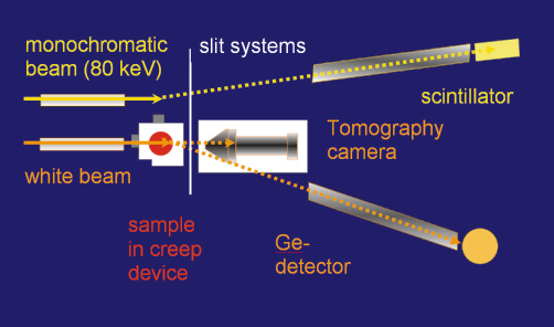
Combining for the first time tomography and diffraction within the same experiment, the creep void evolution in CuZn40Pb2 brass (an ![]() /ß-brass) and its correlation to texture and microstructure development was studied. Sample and experimental conditions were selected in such a way that the timescale of the creep process is much longer than the time required for collecting the microtomography data and the diffraction data. A novel miniature creep device was developed where the path of the incoming and the emerging X-rays over a complete 180° turn of the sample is identical. The experimental setup at beamline ID15A consisted of three detection systems, which allowed us to sequentially perform white beam tomography [2], energy-dispersive diffraction and angle-dispersive diffraction without further alignment or calibration procedures during the experiment (Figure 40).
/ß-brass) and its correlation to texture and microstructure development was studied. Sample and experimental conditions were selected in such a way that the timescale of the creep process is much longer than the time required for collecting the microtomography data and the diffraction data. A novel miniature creep device was developed where the path of the incoming and the emerging X-rays over a complete 180° turn of the sample is identical. The experimental setup at beamline ID15A consisted of three detection systems, which allowed us to sequentially perform white beam tomography [2], energy-dispersive diffraction and angle-dispersive diffraction without further alignment or calibration procedures during the experiment (Figure 40).
 |
|
Fig. 40: The experimental setup at beamline ID15A. |
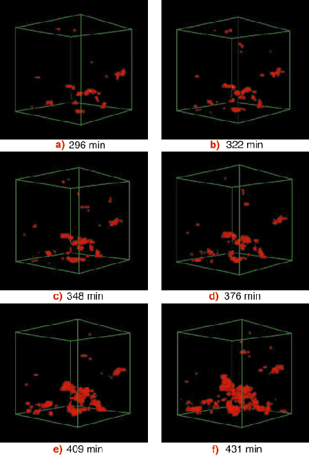
The results of the tomography showed that the sample (initially pre-deformed 4.47% at room temperature) contained some small voids oriented in the longitudinal direction of the sample. With increasing creep time, further voids nucleated and the number and size of the voids increased (Figure 41). In longitudinal slices void chains are visible that form void networks preferentially oriented app. 90° to the sample longitudinal axis, presumably along grain boundaries and along phase boundaries between ![]() and ß-brass. Voids coagulated and subsequently micro cracks became visible. Detailed investigations revealed that the void volume versus creep time obeyed an exponential growth law.
and ß-brass. Voids coagulated and subsequently micro cracks became visible. Detailed investigations revealed that the void volume versus creep time obeyed an exponential growth law.
Analyses of the integrated intensity of the ![]() and ß-brass reflections revealed the formation of a fibre texture during the creep process, which became strong once the pore volume increases substantially. The diffractograms obtained with white high energy synchrotron radiation revealed that the full width at half maximum (FWHM) of all reflections decreased in the early stage of the creep processes due to an annihilation of the dislocations produced by the pre-deformation of the sample. Later, the FWHM remained constant revealing an equilibrium state of dislocation generation and annihilation. The reflection profiles obtained using monochromatic high-energy synchrotron radiation additionally showed grain growth with increasing creep time.
and ß-brass reflections revealed the formation of a fibre texture during the creep process, which became strong once the pore volume increases substantially. The diffractograms obtained with white high energy synchrotron radiation revealed that the full width at half maximum (FWHM) of all reflections decreased in the early stage of the creep processes due to an annihilation of the dislocations produced by the pre-deformation of the sample. Later, the FWHM remained constant revealing an equilibrium state of dislocation generation and annihilation. The reflection profiles obtained using monochromatic high-energy synchrotron radiation additionally showed grain growth with increasing creep time.
 |
|
Fig. 41: Progression of the voids (red) with increasing creep time within a sample of CuZn40Pb2 brass. |
In conclusion the experiment revealed that using synchrotron radiation tomography, void growth kinetics during creep could be studied in the bulk material in situ for the first time. The access to three-dimensional bulk information allowed a quantitative determination of void size and void shape evolution during creep. Combined diffraction and tomography experiments in future will also allow observations of other damage processes such as changes in the stress field and plastic zone around growing cracks or load partitioning, deformation and fracture in multiphase materials.
References
[1] J.-Y. Buffière, E. Maire, P. Cloetens, G. Lormand, R. Fougères, Acta Mat. 47, 1613-1625 (1999).
[2] M. Di Michiel, J.M. Merino, D. Fernandez-Carreiras, T. Buslaps, V. Honkimäki, P. Falus, T. Martins, O. Svensson, Rev. Sci. Inst., 76, 1-7 (2005).
Principal Publication and Authors
A. Pyzalla (a,b), B. Camin (c), T. Buslaps (d), M. Di Michiel (d), H. Kaminski (a), A. Kottar (a), A. Pernack (c), W. Reimers (c), Science, 308, 92-95 (2005)
(a) Institute of Material Science and Technology, TU Wien (Austria)
(b) MPI for Iron Research, Düsseldorf (Germany)
(c) Institut of Material Science and Technology, TU Berlin (Germany)
(d) ESRF


