- Home
- Users & Science
- Scientific Documentation
- ESRF Highlights
- ESRF Highlights 2011
- X-ray imaging
- Insights into structured catalysts for hydrogen production by microscopic synchrotron techniques
Insights into structured catalysts for hydrogen production by microscopic synchrotron techniques
The steam reforming of methane (CH4 + H2O ![]() CO + 3H2) is the most widespread process to large scale H2 production. The reactor consists of multitubes filled with heterogeneous catalysts, mainly nickel supported on a ceramic material such as MgAl2O4 or Al2O3, which increases the velocity of the reaction. Steam reforming is highly endothermic, it operates at high temperatures (around 900°C) and therefore a large amount of heat must be supplied. However, thermal gradients take place within the catalytic bed, causing a decrease in catalytic performance and in the reactor tubes lifetime.
CO + 3H2) is the most widespread process to large scale H2 production. The reactor consists of multitubes filled with heterogeneous catalysts, mainly nickel supported on a ceramic material such as MgAl2O4 or Al2O3, which increases the velocity of the reaction. Steam reforming is highly endothermic, it operates at high temperatures (around 900°C) and therefore a large amount of heat must be supplied. However, thermal gradients take place within the catalytic bed, causing a decrease in catalytic performance and in the reactor tubes lifetime.
Metallic structured catalysts, made of a metallic foam coated by a catalyst, enhance the heat transfer and therefore the efficiency of the process. In particular we have used FeCrAlY foams coated with a nickel catalyst. The coating was performed by a novel electrosynthesis method [1]. It consists of the generation of a catalyst precursor by applying a cathodic potential at the FeCrAlY foam, which is immersed in a solution containing Ni(NO3)2 and Al(NO3)3, with KNO3 as supporting electrolyte. The cations precipitate on the surface of the electrode as layered hydrotalcite-type compounds. Catalysts are obtained by calcination of this precursor at 900°C. The nature of the coating depends on the potential applied and the synthesis time. The structural characterisation of the catalytic film, which is of key importance for the development of the catalysts, cannot be done by conventional XRD techniques because of the complex nature of the support and the thin layer.
We characterised bare and coated FeCrAlY foams at different length scales by absorption tomography at beamline ID19, µ-XRF/XRD tomography at beamline ID22 with a 3.4 x 1.8 µm beam and by submicroscopic XRF measurements (nano-XRF tomography) using a 100 × 130 nm focal spot size at the ID22n endstation to complete the information obtained by SEM/EDS. The different stages in the life of a catalyst, after electrosynthesis, calcination and catalytic tests, were studied.
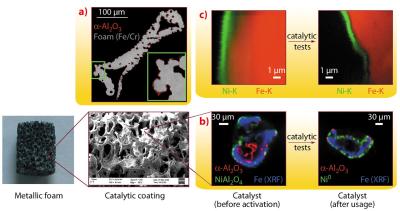
Absorption tomography of a calcined bare foam revealed the presence of a thin layer coating both the inner and outer surface of the hollow FeCrAlY foam (Figure 134a); however, after coating it was not possible to distinguish between the catalyst and this layer. Complementarily, µ-XRF/XRD tomography of foam struts (Figure 134b) gave information about the nature and the spatial distribution of the crystalline phases in the catalytic coating (NiO and NiAl2O4), both of them located on top of an α-Al2O3 layer as observed by XRD. The distribution of NiO appeared not to be homogeneous as it was present in the zones where a large amount of Ni was deposited as confirmed by XRF. After catalytic tests, the coating remained on the support and an intermixed layer containing Ni0, γ/η-Al2O3 and α-Al2O3 phases was identified, confirming that a stable active layer was formed.
However, the layer thicknesses could not be estimated since they were of the same order as the size of the primary X-ray beam. The actual thickness of the catalytic layer was obtained by nano-XRF mapping and tomography of strut cross-sections (Figure 134c). The hydrotalcite precursor was formed by a 1 µm film in which we also observed some potassium, originating from the supporting electrolyte. After calcination the layer thickness decreased by a half, whereas after catalytic tests no further decrease was observed. The gap in between the foam and the nickel arose from the intermediate Al2O3 layer, which was not visible by XRF in air.
In summary, tomographic measurements (X-ray absorption, µ-XRF/XRD and nano-XRF) allowed the characterisation of “as made” catalysts at different length scales, obtaining information about the distribution of the phases and the elements, important parameters for further development of these structured catalysts.
Principal publication and authors
P. Benito (a), W. de Nolf (b), S. Bugani (a), F. Basile (a), G. Fornasari (a), K. Janssens (b), E. Scavetta (c), D. Tonelli (c) and A. Vaccari (a), Adv. Funct. Mater. 20, 4117–4126 (2010).
(a) Dip. Chimica Industriale e dei Materiali, University of Bologna (Italy)
(b) Department of Chemistry, University of Antwerp (Belgium)
(c) Dip. Chimica Fisica e Inorganica, University of Bologna (Italy)
References
[1] F. Basile, P. Benito, G. Fornasari, V. Rosetti, E. Scavetta, D. Tonelli and A. Vaccari, Appl. Catal. B: Env. 91, 563–572 (2009).


