- Home
- Users & Science
- Scientific Documentation
- ESRF Highlights
- ESRF Highlights 2011
- Structure of materials
- A new dimension in short fatigue crack characterisation
A new dimension in short fatigue crack characterisation
If you bend a piece of metal, like a spoon, just a tiny little bit, so that it returns back to its original shape when you let go, nothing seems to have happened. But on the microscopic scale, unobservable to the naked eye, some permanent deformation will occur in its crystalline structure. If you repeat this process millions of times, the spoon may eventually break. In materials science and engineering this phenomenon is called fatigue. The risk of failure of stressed components due to cyclic loading has great practical importance, for instance in engines, railway wheels and structures such as bridges that vibrate due to traffic or wind. A deep understanding of fatigue mechanisms is needed to increase the reliability of predictions such as the fatigue lifetime and to design materials with greater fatigue resistance.
A fatigue crack in a structural component, such as part of an engine, may spend up to 90% of its lifetime as a “short” fatigue crack. Such cracks are typically smaller than 1 mm, and are quite difficult to detect. Their behaviour is also less well understood than longer cracks. The local effects of the microstructure average out gradually with increasing crack length, so long crack growth rates in response to loading can be predicted by empirical laws. For short cracks the situation is more complex: the elastic and plastic anisotropy of crystalline materials create heterogeneities in the deformation at the grain and sub-grain level and these govern short-crack growth. The 3D nature of the microstructure, particularly grain shape and crystal orientation, must be taken into account for accurate predictive modelling. The proper characterisation and description of microstructure and the subsequent modelling of short crack behaviour are complicated!
To acquire a full description of short fatigue crack growth, a multi-dimensional dataset is required: for each point in three dimensional space, the three dimensional grain orientation and the three-dimensional crack growth vector with time must be known. Previously, it was only possible to characterise crack growth and microstructure at the surface or through destructive, three-dimensional mapping of the crack shape and microstructure at a single moment in time. Characterisation of the crucial extra dimensions has now been achieved at beamlines ID19 and ID11, due to the development of diffraction contrast tomography [1]. This non-destructive method makes it possible to characterise grain orientations and boundaries within the bulk of polycrystalline materials. Information on the 3D crack evolution with time is gained by observing the crack with phase contrast tomography [2], at intervals with progressive fatigue cycling.
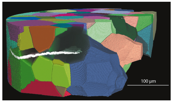
Figure 33 shows an example of the combined data.
 |
|
Fig. 33: Short fatigue crack in a polycrystalline sample. The grains and the crack were reconstructed using diffraction and phase contrast tomography. |
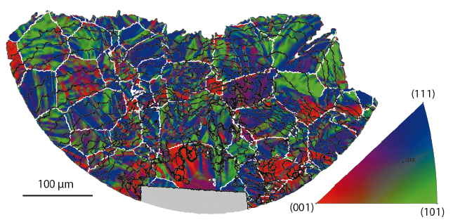
An approach was developed for the data analysis that presents information as colours on the surface of the 3D crack (Figure 34). For each part of the crack, the local crystal orientation, the number of fatigue cycles required to develop the crack to that point and the grain in which it is situated can be determined. This enables the calculation of local crack growth rates, the crystallographic aspects of the fracture surface and the relative changes in crystal orientation at grain boundaries. Using this toolbox, the interactions between crack and microstructure that control its overall development can be studied for the first time in full depth.
Principal publication and authors
M. Herbig (a,b), A. King (c), P. Reischig (d), H. Proudhon (e), E. M. Lauridsen (f), J. Marrow (g), J.-Y. Buffière (a) and W. Ludwig (a,h), Acta Mat. 59, 590–601 (2011).
A. King (h), W. Ludwig (a, h), M. Herbig (a, b), J.-Y. Buffière (a), A.A. Khan (i), N. Stevens (j) and T.J. Marrow (g), Acta Mat. 59, 6761-6771 (2011).
(a) Université de Lyon, MATEIS, UMR5510 CNRS, Villeurbanne (France)
(b) Present address: Max-Planck-Institut für Eisenforschung, Düsseldorf (Germany)
(c) GKSS-Research Centre, Geesthacht (Germany)
(d) Karlsruhe Institute of Technology, Eggenstein-Leopoldshafen (Germany)
(e) MINES ParisTech, Centre des Matériaux, CNRS UMR 7633, Evry (France)
(f) Risø-DTU, Technical University of Denmark, Roskilde (Denmark)
(g) Department of Materials, University of Oxford (UK)
(h) ESRF
(i) Pakistan Institute of Nuclear Science & Technology, Islamabad (Pakistan)
(j) Manchester Materials Science Centre (UK)
References
[1] W. Ludwig, P, Reischig, A. King, M. Herbig, E. Lauridsen, T. Marrow and J. Buffière, Rev. Sci. Instrum. 80, 033905 (2009).
[2] P. Cloetens, M. Pateyron-Salomé, J.-Y. Buffière, G. Peix, J. Baruchel, F. Peyrin and M. Schlenker, J. Appl. Phys 81, 5878-5886 (1997).


