- Home
- Users & Science
- Find a beamline
- Complex systems and biomedical sciences
- ID10 - Soft interfaces and coherent scattering beamline
- ID10 EH2
- ID10 EH2 Beamline Description
ID10 EH2 Beamline Description
Description of the ID10 (EH2) beamline
[ schematic layout | undulator source | focussing and filtering | polarization and coherent properties | data acquisition and beamline control | EH2 station | EH2 optics | EH2 instrumentation | applications | technical information ]
The ID10 beamline is located at insertion device port ID10. It comprises two experimental stations: EH1 and EH2. The undulator source, the Front-End and the Optics-Hutch OH1 are common for both beamline branches (EH1 and EH2).
Schematic Layout
The schematic layout of the ID10 beamline is shown in Figure 1. The frontend (FE), located 26 m from the insertion device (ID) interfaces the beamline to the storage ring and contains the main beam shutter, a diamond window (300 µm). The first safety hutch (Optics-Hutch) houses the primary slits (PS), a beam diagnostics device (BPM), a white beam double mirror in horizontal reflection geometry, a cryo-cooled channel-cut monochromator for the EH1 mainly, a pair of secondary slits (SS), a white beam transfocator, double mirror in vertical reflection geometry and a photon white beam shutter unit (PSh).The white/pink beam passes in a pipe through the EH1 experimental hutch and enters into the OH3 optics-Hutch and then EH2 experimental station.
|
|
|
Fig. 1: Schematic layout of the ESRF ID10 beamline. |
The OH3 optics-hutch contains beryllium compound refractive lenses (CRL), ternary slits (TS), the water cooled pseudo channel-cut monochromator and a photon shutter module (PSh). The pseudo channel-cut monochromator is located at 56 m from the source contains a well polished Si(111) crystal and operates in vertical scattering geometry.
The Undulator Source
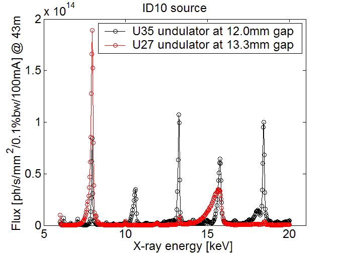
The beamline uses three undulator segments in series: one 27 mm undulator (U27), one 35 mm undulator (U35), and a revolver unit carrying both U27 and U35 undulators. Hence the source consists of either 2xU27+U35 or 2xU35+U27 depending on the energy requirements. All undulators are installed in series in the ID10 high-β straight section. The source size (FWHM) for the 3.9 nm lattice and 1% coupling is 928 µm (horizontal) and 23 µm (vertical). The electron beam divergences are 24 µrad (h) and 9 µrad (v) . The divergence of the photon beam depends on the length of the undulator, the photon energy, the energy spread of the electron beam and the undulator tuning. Typical divergences (FWHM) at 10 keV are 28 µrad (h) and 17 µrad (v) implying a maximum beam size of 2 mm (h) x 0.8 mm (v) at 44 m from source. The total emitted power from a single undulator is 1.14/2.05 kW (U27/U35 @ 100 mA) and the maximum power density in the central cone at 27 m distance is 66 W/mm2 for both undulators at 100mA ring current. Figure 2 shows undulator spectra taken with a Si monochromator crystal. The spectra have been corrected for absorption by Be and diamond windows. More details about the UNDULATOR SOURCE
 |
|
Fig. 2: Flux spectra of the ID10 undulators tuned to produce 8 keV photons (U27: 1st harmonic, U35: 3rd harmonic). The spectra were recorded with a Si (111) crystal in symmetric Bragg scattering geometry. |
Focussing and Filtering
Beam focussing in the EH2 is provided by either the beryllium compound refractive lenses (CRL) in OH3 or by the transfocator in OH1. They can provide a 8 keV vertically focussed beam in Troika I (46 m from source) or Troika III (61 m from the source). A white beam double mirror system in horizontal reflection geometry (29 m from source) is used to reject high undulator harmonics and reduce the heat load on the pseudo channel-cut monochromator. Both mirrors are separated into three stripes uncoated Si, Pt-coating and Pd-coating providing a harmonics free
monochromatic beam in the energy range of 7-30 keV with the fixed exit geometry (horizontal offset: 3.2 mm). Filtering of the beam can also be achieved by introducing flat mirrors in the monochromatic beam at the individual stations.
Polarization and Coherence Properties
The measured degree of linear horizontal polarization at 9.1 keV is 1.00-0.02 for a 2x2 µrad2 beam and 0.97±0.02 for a 10x10 µrad2 beam. A waveplate assembly operating a diamond crystal in either quarterwave or halfwave mode can allow to produce circular polarization or linear polarization in the verical plane. Partially coherent X-rays can be produced by appropriate collimation and by illuminating collimating pinhole apertures (typical diameter 10 µm at a distance RS=46 m from the source with size dS) with monochromatic X-rays provided by a Si(111) monochromator. A transverse coherence length of λRS/2dS ~10 µm and a longitudinal coherence length of λ2/2Δλ ~1 µm can be achieved for λ=1.5 Å. The coherent flux through a 10 µm pinhole is typically 4x10¹⁰ photons/sec at 100 mA storage ring current. Coherent X-ray beams are routinely used to record static X-ray speckle patterns from disordered materials and for the study of their slow dynamics via X-ray Photon Correlation Spectroscopy (XPCS).
Data Acquisition and Beamline Control
The present detector environment involves scintillation counters (Cyberstar), Avalanche Photo Diode (APD) detectors, and CCD detectors, Medipix-2 and Maxipix 2x2 pixel array detector. The CCDs are both Andor Ikon-M cameras with 1024 x 1024 pixels and a pixel size of 13 µm. The device is a deep depletion detector that is used in direct illumination mode enabling single photon counting in XPCS mode. The Medipix-2 is a CMOS detector with 55 μm pixel size and an active area 256×256 pixels. It can operate at 1kHz full frame rate. High dynamic range (2×10⁵ count/s/pixel), single photon counting and noiseless read-out make this detector ideal for the beamline applications. The detector is mostly used to measure millisecond and slower dynamics. The Maxipix 2x2 is a 4 module version of the Medipix-2 detector with an active area 516×516 pixels and 300Hz full frame rate. Due to the large active area this detector is used for XPCS and more importantly for CXDI. High counter depth (11180 counts) in combination with fast read-out allows us to register spectra with essentially unlimited dynamic range. This is achieved in the so-called accumulation mode in which the device server takes frames with short exposure time (50ms) and adds them to produce a single image with the desired total exposure time. Digital autocorrelators (correlator.com and ALV) is available for X-ray Photon Correlation Spectroscopy (XPCS) experiments with coherent X-rays. For more information about correlators and detectors we refer to the user guide section about DETECTORS AND CORRELATORS. All beamline and diffractometer motions are achieved via stepping motors. The beamline is controlled with a VME system and supported by UNIX workstations/Linux PCs. Monochromator and diffractometer are controlled via the spec software package interfaced into the VME system. Basic software for data analysis and data transfer is available on the Workstation and on Window based PCs.
The EH2 Station
The EH2 end-station is part of the ID10 beamline. It is optimized for scattering experiments with coherent X-ray beams but can also support "pink" beam experiments. Coherent photons are available in a Δλ/λ=10-4 bandwidth configuration via a silicon (111) pseudo channel-cut monochromator for standard XPCS experiments and in the broader "pink" beam mode 8 keV, Δλ/λ=10-2 via white beam double mirror for SAXS experiments with coherent X-rays.
The general layout of the EH2 station is shown in Figure 1. It consists of two independent hutches, a small local optics-hutch OH3 and the main Experimental hutch EH2. The first shutter of EH2 is located at the end of the OH1 optics-hutch. After this shutter the beam travels through a pipe and enters the OH3 optics-hutch . Here it passes through a ternary slits (TS) and impinges on a Si (111) pseudo channel-cut monochromator diffracting in the vertical plane. A shutter (PSh) at the hutch exit separates the Optics hutch OH3 from the Experimental hutch EH2 allowing to keep the optics under permanent illumination contidions and avoiding heat related drifts. The EH2 hosts the main instrumentation in an almost fixed configuration. The beam is guided to the sample position on the four-circle Huber diffractometer located 60.8 m from the source. In the small-angle scattering configuration the scattered photons, guided by a 3-7m long flight tube, reach the detector stages located on an optical bench.
EH2 Optics
The EH2 Optics hutch OH3 is equipped with a Si (111) pseudo channel-cut monochromator diffracting in the vertical plane in the range 6-24 keV. It is made out of a well polished silicon crystal and is water cooled. A motor can push on the second Si blade to compensate for the Bragg angle change of the first crystal due to the thermal load. Focussing and filtering can be performed by use of the elements described above in the FOCUSSING AND FILTERING section.
EH2 Instrumentation
The EH2 instrumentation is organized around two granite tables and a 1.8m long optical bench:
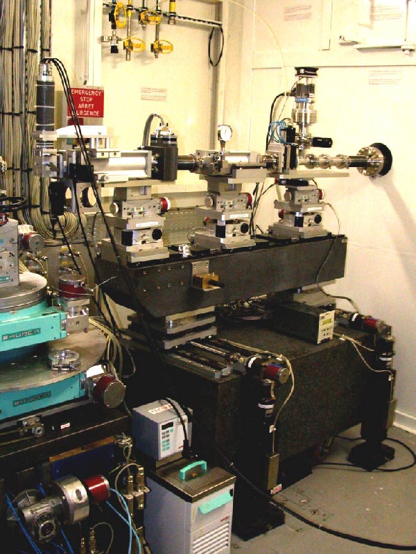
- On the first granite table (Figure 3) a flight path guides the beam to the sample position.
 |
|
Fig. 3: EH2 1st granite table. |
It consists of three small X95 profiles clamped on elevators and contains a local absorber unit, a local deflecting mirror (elevator z1, z2) and a pair of slits. The settings of the slit is controlled by four motors cshg (horizontal gap), csho (horizontal offset), csvg (vertical gap), csvo (vertical offset). The settings of the slit is controlled by four motors rghg (horizontal gap), rgho (horizontal offset), rgvg (vertical gap), rgvo (vertical offset). The assembly is evacuated and separated by a water-cooled well polished Be window from the OH3 vacuum. The local mirror and the slits can be translated perpendicular to the beam by y1,y2 and y3 translations respectively. The translations xtf and xtb can move/rotate the flight path in the horizontal plane up to 200mm/5°. - On the second granite table (Figure 4) a four-circle Huber diffractometer in horizontal scattering geometry is located.
 |
|
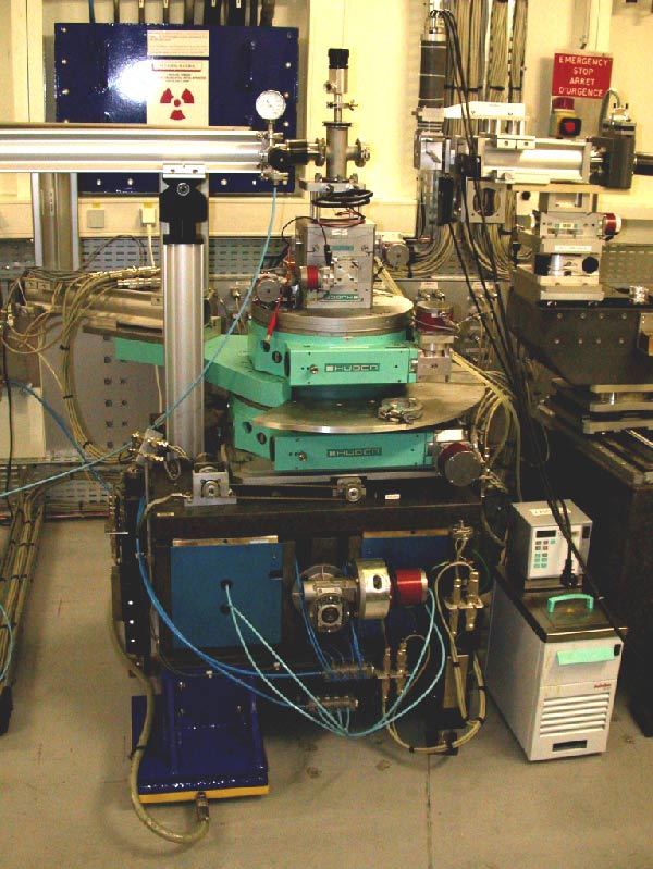
Fig. 4: EH2 diffractometer. |
The diffractometer sits on the horizontal translation ydif that allows for a precise positioning of its center of rotation into the beam. The height of the diffractometer can be varied by either moving the three jacks jdfl, jdfr and jdb underneath the granite table with one pseudo motor jdz. The system allows for a vertical displacement of 30mm. The sample stage is equipped with a goniometer head (x-y translations/double tilt assembly). The goniometer head can be equipped with a small-angle cryostat (70K-293K), a small-angle scattering chamber, furnace (300-1000K) for wide angle experiments or any compatible user instrumentation. The whole granite table can be moved along the beam via compressed-air pads. - The detector table ( Figure 5) is especially designed for carrying the detector equipment for small-angle scattering experiments.
 |
|
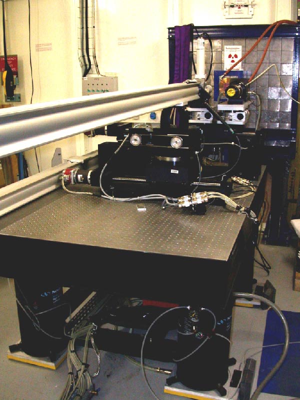
Fig. 5: The detector table carrying the detector assembly at EH2. |
It hosts two elevators (zdet and zccd) carrying a point detector and a 2D detector on the horizontal translation ydet and a third y-z unit (ypipe, zpipe) able to hold an evacuated 3-7 m long flight tube. At the inner side of the exit window of the flight tube a tantalum beam-stop can be inserted to block the direct beam. It can be mounted in vertical, horizontal and 45° position and translate in the radial direction (motor bst). The detector table can be moved by a compressed air pads system. The Experimental hutch is air-conditioned and provides basic supplies (water, pressurized air, nitrogen gas, low-flow extraction). Simple sample-environment equipment and space for preparation of experiments is available in an adjacent laboratory.
Applications
Scattering with coherent X-rays
X-ray photon correlation spectroscopy (XPCS) probes the dynamic properties of matter by analyzing the temporal correlations among photons scattered by the studied material. It measures the low frequency dynamics (108 Hz to 10-3 Hz) in a Q range from typically 1x10⁻³ Å-1 up to several Å-1. It utilizes a partially coherent X-ray beam (E= 8 keV, Δλ/λ=1.4x10-4, 10x10 µm2 beamsize, 4x10¹⁰ ph/s/100mA). Experiments are carried out either in SAXS, WAXS or in grazing incidence scattering geometry. Temporal autocorrelation functions are measured by coupling a point detector (typically 100x100 µm2 aperture) to a digital autocorrelator giving fast access to the correlation function over a wide range of correlation times (10-8 sec to 1000 sec) at a single Q value. Aquisition times are typically in the order of 1-60 minutes per correlation function depending on the count-rate. Typical applications are the time-dependence of equilibrium critical fluctuations and the low frequency dynamics in disordered hard (e.g. non-equilibrium dynamics in phase separating alloys or glasses) and soft condensed matter materials, in particular complex fluids (e.g. hydrodynamic modes in concentrated colloidal suspensions, capillary mode dynamics in liquids, layer-fluctuations in membranes and equilibrium dynamics in polymer systems).
Coherent diffraction imaging is a high-resolution imaging technique. It uses an iterative phase retrieval algorithm to reconstruct an image of an isolated object from oversampled diffraction pattern alone. The diffraction pattern is measured by the Maxipix 2x2 detector. Individual 2D diffractions at different sample tilts can be assembled in a 3D diffraction volume and the full 3D image is reconstructed using iterative software available at the beamline. The typical size of the object is 7-0.8 µm and the image voxel size is 32-5 nm depending on the sample size. Data acquisition of the 3D diffraction volume takes 2-10 hours depending on the sample scattering power.
Technical Information (EH2)
| scientist in charge |
Yuriy Chsuhkin tel:+33 (0)4 76 88 21 98 |
|||||||||
| scientific applications | Optimized for scattering with partially coherent X-ray beams (7-24keV): X-ray Photon Correlation Spectroscopy (XPCS) and Coherent Diffraction imaging (CDI) | |||||||||
| source parameters | high β straight section; three undulator segments in series: U27, U35 and a U27/U35 revolver unit. | |||||||||
| U27 undulator | U35 undulator | |||||||||
| λu | 27 mm | 35 mm | ||||||||
| Kmax | 5.0 | 6.5 | ||||||||
| field Bmax | 2 T | 2 T | ||||||||
| source size | 928 x 23 µm2 (HxV) FWHM | |||||||||
| source divergence | 28 x 17 µrad2 (HxV) FWHM @ 10keV | |||||||||
| peak brilliance | > 1020 ph s-1mrad-2mm-2 (0.1% bw, 100 mA @ 8 keV) | |||||||||
| power | 1.14/2.05 kW @ 100mA ring current (single U27/U35) | |||||||||
| power density | 66 W mm-2 (single U27 or U35) @ 27 m distance from source and 100 mA ring current | |||||||||
| optics | PS | Mirrors | Mono I | SS | Transfocator | CRL | TS | Mono II | ||
| distance from source [m]: | 27 | 30 | 30.2 | 34 | 36 | 53.7 | 54.5 | 56.5 | ||
| focusing: | 2 Be CRL @ 24 m from source (FE) for vertical focussing in Troika and Troika III (8keV) | |||||||||
| beam size at sample: | max. 2 x 0.8 mm2, min. 10 x 10 µm2 (HxV) | |||||||||
| intrinsic resolution ΔE/E: | 1.4 x 10⁻⁴ silicon (111) | |||||||||
| flux at sample: | About 5 x 10 13 ph/s/mm2 (8 keV) depending on the monochromator crystal chosen | |||||||||
| detectors | scintillation counters, APD detectors, CCD detectors, Maxipix 2x2, Medipix | |||||||||
| beamline control | UNIX Workstation, Linux PC, SPEC control software | |||||||||
| ancillary equipment | SAXS chamber, SAXS cryostat, furnace, autocorrelator etc. | |||||||||


