- Home
- News
- Spotlight on Science
- Seeing inside a...
Seeing inside a working catalyst
19-12-2011
Metal/metal oxides supported on porous catalyst bodies represent the cornerstone of the heterogeneous catalysis industry. However, little is known about the process by which an active phase forms from an impregnation precursor and how this influences the final properties of the catalyst. Using dynamic X-ray diffraction computed tomography at beamline ID15, real time insight into both the catalyst evolutionary process and the stability of the catalyst under reaction conditions has been obtained for the first time in both two and three dimensions.
Share
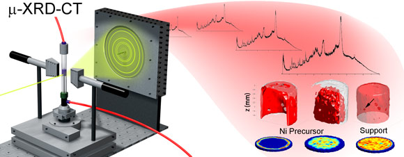
Industrial catalysis typically uses mm-sized catalyst bodies in fixed bed reactors. The efficiency of the final catalytic system depends on the nature and distribution of metal/metal oxide ‘active species’ within the catalyst body. However, this can be affected during the multi-step preparation process and the evolution of the active species from an initial precursor complex, then delivered via liquid phase impregnation, is often a highly convoluted process. In recent times, several analytical techniques have been used to obtain real time 2D and 3D spatial information on the nature of chemical species present on the catalyst during preparation in order to identify the key physicochemical processes that govern both their spatial distribution and final properties. Such information would allow better control over these properties and lead to improvements in catalyst performance [1]. Recently we employed the novel technique of synchrotron X-ray diffraction computed tomography (XRD-CT) [2] and demonstrated its capability to image a catalyst body as a function of time to follow the preparation process and to study the catalyst as a reaction (CO methanation) takes place (Figure 1).
Catalyst preparation normally involves two or three steps: impregnation of the catalyst body with the active metal in the form of a metal complex, calcination at high temperatures and, in some cases, ‘activation’ in a pre-conditioning gas. XRD-CT was employed to examine this second step (calcination in N2) of a Ni supported γ-Al2O3 catalyst body starting from a NiCl2 source.
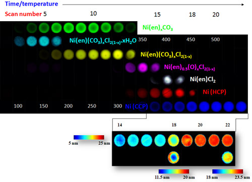
The most important observation was the formation of the cubic (fcc) metallic Ni phases via a number of complex intermediate phases. 2D XRD-CT scans revealed the formation of two different crystalline phases located at the periphery and in the centre of the body accordingly. Although both phases yielded fcc Ni, the precursor at the periphery did so in one step, while the phase in the centre did so via a 3-4 step process (Figure 2). This appeared to affect the physical properties, in particular the particle size of the fcc Ni phase with the fcc Ni particles in the centre of the pellet being larger than those seen at the periphery. This of course has important implications for the activity/selectivity of these catalyst bodies in a catalytic reaction.
In a second recent study, we combined XRD-CT with absorption-CT to study the phase evolution process in NiNO3 impregnated Ni/γ-Al2O3 catalyst bodies during calcination and activation, but more importantly, under real catalytic conditions. As with NiCl2 impregnated catalyst bodies, two different, inhomogenously distributed precursors result from the impregnation process although the breakdown of these precursors resulted in the formation of more uniformly-sized fcc Ni nanoparticles. Particles located towards the periphery undergo uncontrolled sintering on exposure to O2 although this appears to be dependent on both the concentration/distribution of the Ni and its form (it is expected that Ni is present in the sample in both crystalline and diffraction-silent forms). Reduction in H2 did not induce further sintering but results in an active fcc Ni containing catalyst for CO methanation. In operando catalytic measurements performed during CO methanation, demonstrated the crystalline metallic fcc Ni component to be remarkably stable during the duration of reaction (~ 3 hours), undergoing no change in phase constitution, spatial distribution or average particle size, leading us to conclude that metallic fcc Ni is the active component of the catalyst for CO methanation.
Principal publication and authors
Dynamic X-ray diffraction computed tomography reveals real-time insight into catalyst active phase evolution, S.D.M. Jacques (a,b), M. di Michiel (c), A.M. Beale (a), T. Sochi (b), M.G. O’Brien (a), L. Espinosa-Alonso (a), B.M. Weckhuysen (a) and P. Barnes (b), Angew. Chem. Int. Ed. 50, 10148 (2011); Active phase evolution in single Ni/Al2O3 methanation catalyst bodies studied in real time using combined μ-XRD-CT and μ-absorption-CT, M.G. O’Brien (a), S.D.M. Jacques (a,b), M. di Michiel (c), P. Barnes (b), B.M. Weckhuysen (a) and A.M. Beale (a) Chem. Sci. (2011); DOI: 10.1039/C1SC00637A.
(a) Inorganic Chemistry and Catalysis, Debye Institute for NanoMaterials Science, University of Utrecht (The Netherlands)
(b) UCL Chemistry London/ Dept. Crystallography, Birkbeck College, London (UK)
(c) ESRF
References
[1] L. Espinosa-Alonso, A.M. Beale and B.M. Weckhuysen Acc. Chem. Res. 43, 1279 (2010).
[2] P. Bleuet, E. Welcomme, E. Dooryhee, J. Susini, J.L. Hodeau, P. Walter, Nat. Mater. 7, 468 (2008).
Top image: X-ray diffraction computed tomography of a metal/metal oxide catalyst during its preparation.


