- Home
- News
- Spotlight on Science
- Pencil-beam diffraction...
Pencil-beam diffraction microtomography
03-07-2008
A new technique has been developed for the three-dimensional study of microcrystalline samples. It bridges the gap between global quantitative and local compositional techniques.
Share
Powder X-ray diffraction is a technique used to solve new crystalline structures, identify phases, analyse phase transformation, and examine micro-structural features. With the recent improvements in X-ray optics and detection, powder microdiffraction experiments can be carried out that provide researchers with images of high lateral resolution within a reasonable scanning time. However, such two-dimensional mappings only provide a global integral of all the diffracted intensity along the X-ray path. To study bulk materials, we also require depth resolution information. A local structural probe providing depth resolution images is mandatory in cases where the materials present structural heterogeneities. Three-dimensional diffraction tomography has already been demonstrated for various applications: WAXS has been used to study soft tissue achieving millimetre resolution for biological applications, and SAXS has been used to study polymers. Furthermore, Laue diffraction and topotomography have been used to build 3D mappings of individual grains [1, 2].
Here we introduce a new scanning method for synchrotron X-ray diffraction tomography in order to reconstruct cross-section images of unidentified phases in nanomaterials and polycrystalline materials. The technique is a further extension of the X-ray fluorescence microtomography technique that has recently been developed at beamline ID22. It involves simultaneous measurement of the absorption, fluorescence and diffraction data while translating (along y) and rotating (around ω) a sample illuminated by a focused –or pencil– beam (Figure 1). Thanks to the high flux combined with the use of a fast readout and low noise camera (FRELON) equipped with a taper, the scanning time for a 100 µm3 sample is estimated at 6 hours. This process produces a stack of diffraction images, fluorescence spectra and absorption sinograms. The sinograms are a representation (y,ω) of a particular crystalline phase, elemental distribution, and attenuation coefficient, respectively. Starting from the set of sinograms, a mathematical inversion formula gives rise to cross-section images for each of the three modalities.
 |
|
Figure 1. The ID22 sample environment. |
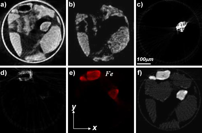
This multi-modal tomographic scheme was first tested on a textbook powder with various grain sizes: a 300 µm capillary was filled with a mixture of chalcedony and iron pigments containing hematite (α-Fe2O3). Chalcedony is composed of long quartz micro-fibres, generally less than 100 nm in diameter. A single cross-section image was measured and reconstructed (Figure 2). Even if chalcedony was by far the dominant phase, at least two types of iron grains were observed: hematite and siderite on the one hand, and hematite and phylosilicate phases including greenalite on the other hand. For each grain, a diffraction diagram can be extracted from extremely tiny volumes of powder (as small as the voxel size), allowing subsequent data simulation or structural refinement.
 |
|
Figure 2. Reconstructed cross-sections corresponding to: a) the entire diffracted intensity; b) chalcedony; c) hematite and siderite; d) hematite and greenalite; e) fluorescence imaging; f) absorption imaging. |
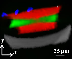
Another carbon-based sample with similar compositions and density was also analysed. Five phases were identified and located within it (Figure 3). Well-crystallised cubic diamond was located in the central part of the sample, embedded within an amorphous carbon sp3 phase matrix. Furthermore, located at the sample surface, crystallised ferrite (α-Fe) grains were identified as well as one single impurity grain of calcite (CaCO3), outlining the sensitivity of the method. Ferrite comes from some contamination by the razor blade during sample extraction, while calcite is probably a dust particle in contact with the pressure cell. For this weakly absorbing material, absorption and fluorescence tomography do not provide any contrast, while diffraction tomography reveals the distribution of phases (crystalline and amorphous) inside the sample.
 |
|
Figure 3. Cross-section reconstruction of the diamond sample. Glass capillary (gray), sp3 amorphous (red), cubic diamond (red), ferrite (blue) and calcite (white). |
Pencil-beam diffraction tomography bridges the gap between the global quantitative structural probe, such as X-ray and neutron diffraction methods, and the local compositional probe, such as X-ray fluorescence and absorption computed-tomography techniques or electron diffraction. Though limited by the number of crystallites in the gauge volume and their size, this method presents a number of advantages. It can obtain contrast where other modalities cannot, provide multi-modal images for a complete sample characterisation and allow the reconstruction of unknown crystalline phases without any a priori information. Furthermore, it is extremely sensitive due to the quantity of diffraction images recorded at different positions and angles of the sample.
References
[1] W. Ludwig, E.M. Lauridsen, S. Schmidt, H.F. Poulsen, J. Baruchel, High-resolution three-dimensional mapping of individual grains in polycrystals by topotomography, J. Appl. Cryst., 40, 905-911 (2007).
[2] B.C. Larson, W. Yang, G.E. Ice, J.D. Budai and J.Z. Tischler, Three-dimensional X-ray structural microscopy with submicrometre resolution. Nature 415 887-890 (2002).
Principal publication and authors
P. Bleuet (a), E. Welcomme (b) , E. Dooryhée (c), J. Susini (a), J-L. Hodeau (c), Ph. Walter (b), Diffraction-Tomography: A local structural probe for heterogeneous diluted materials, Nature Materials 7, 468 - 472 (2008).
(a) ESRF
(b) Centre de Recherche et de Restauration des Musées de France, CNRS-UMR 171, Palais du Louvre, Paris (France)
(c) Institut Néel, CNRS-UPR 2940, Grenoble (France)
partners


European Synchrotron Radiation Facility - 71, avenue des Martyrs, CS 40220, 38043 Grenoble Cedex 9, France.